Download
1 / 62
690 likes | 1.83k Views
COE 341: Data & Computer Communications (T061) Dr. Radwan E. Abdel-Aal Chapter 4: Transmission Media Agenda Overview Guided Transmission Media Twisted Pair Coaxial Cable Optical Fiber Wireless Transmission Antennas Terrestrial Microwaves Satellite Microwaves Broadcast Radio Infrared

E N D
COE 341: Data & Computer Communications (T061)Dr. Radwan E. Abdel-Aal Chapter 4: Transmission Media
Agenda • Overview • Guided Transmission Media • Twisted Pair • Coaxial Cable • Optical Fiber • Wireless Transmission • Antennas • Terrestrial Microwaves • Satellite Microwaves • Broadcast Radio • Infrared
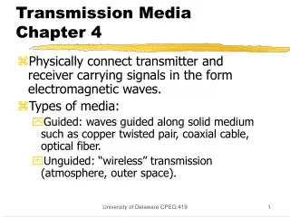
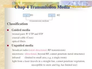
Overview • Media: • Guided – wire or fiber • Unguided - wireless • Transmission characteristics and quality determined by: • Signal • Medium • For guided, the medium is more important • For unguided, the bandwidth provided by the antenna is more important
Design Issues • Key communication objectives are: • High data rate • Low error rate • Long distance • Bandwidth economy: Tradeoff - Want larger BW for higher data rates: C B - But limited by economy: Larger BW is costly e.g. Coaxial Vs TP • Transmission impairments • Attenuation: Twisted Pair > Cable > Fiber (best) • Interference: Worse with unguided… (the medium is shared!) • Number of receivers • In multi-point links of guided media: More connected receivers introduce more attenuation
The Electromagnetic Spectrum Microwaves Light 10 GHz 100 MHz 10 KHz
Standard Multiplier Prefixes 1-18 to 10+18 exa- E 1018 = 1,000,000,000,000,000,000 peta- P 1015 = 1,000,000,000,000,000 tera- T 1012 = 1,000,000,000,000 giga- G 109 = 1,000,000,000 mega- M 106 = 1,000,000 kilo- K 103 = 1,000 milli- m 10-3 = 0.001 micro- 10-6 = 0.000,001 nano- n 10-9 = 0.000,000,001 pico- p 10-12 = 0.000,000,000,001 femto- f 10-15 = 0.000,000,000,000,001 atto- a 10-18= 0.000,000,000,000,000,001
Ultra violet, X-Rays, Gamma-Rays Electromagnetic Spectrum Used for Communications
Study of Transmission Media • Physical description • Main applications • Main transmission characteristics
Guided Transmission Media • Twisted Pair • Coaxial cable • Optical fiber
Frequency Range Typical Attenuation Typical Delay Repeater Spacing Twisted pair (with loading coils) 0 to 3.5 kHz 0.2 dB/km @ 1 kHz 50 µs/km 2 km Twisted pair(No loading coils) e.g. for ADSL 0 to 1 MHz 0.7 dB/km @ 1 kHz 5 µs/km 2 km Coaxial cable 0 to 500 MHz 7 dB/km @ 10 MHz 4 µs/km Up to 9 km Optical fiber 186 to 370 THz 0.2 to 0.5 dB/km 5 µs/km 40 km Transmission Characteristics of Guided Media: Overview • Same delay (except with loading) Fewer Repeaters Required Lower Attenuation Larger Operating Frequencies
Twisted Pair (TP) Effect of loading with coils in series at intervals But attenuation rises rapidly Outside this narrow band. No good for ASDL which tries to get 1 MHz BW from the TP line! Flat and low attenuation Over the telephone voice band (300-3400 Hz) (Passive Equalizer)
UTP Cables unshielded
Twisted Pair - Applications • Most commonly used guided medium • Telephone network (Analog Signaling) • Between houses and the local exchange (subscriber loop) • Originally designed for analog signaling. Digital data transmitted using modems at low data rates • Within buildings (short distances): (Digital Signaling) • To private branch exchange (PBX) (64 Kbps) • For local area networks (LAN) (10-100Mbps) Example: 10BaseT: Unshielded Twisted Pair, 10 Mbps,100m range Digital signal travels in its base band i.e. without modulating a carrier (short distances)
Twisted Pair - Pros and ConsCompared to other guided media Pros: • Low cost • Easy to work with (pull, terminate, etc.) Cons: • Limited bandwidth • Limited data rate • Large Attenuation • Limited distance range • Susceptible to interference and noise (exposed construction)
Twisted Pair - Transmission Characteristics • Analog Transmission • For analog signals only • Amplifiers every 5km to 6km • Bandwidth up to 1 MHz (several voice channels): ADSL • Digital Transmission • For either analog or digital signals (carrying digital data) • Repeaters every 2km or 3km • Data rates up to few Mbps (1Gbps: very short distance) • Impairments: • Attenuation: A strong function in frequency ( Distortion, need for equalization) • EM Interference: Crosstalk, Impulse noise, Mains interference, etc.
Attenuation in Guided Media Thinner Wires
WK 7 Ways to reduce EM interference • Shielding the TP with a metallic braid or sheathing • Twisting also reduces low frequency interference • Different twisting lengths for adjacent pairs help reduce crosstalk
Unshielded (UTP) and Shielded (STP) • Unshielded Twisted Pair (UTP) • Ordinary telephone wire: Abundantly available in buildings • Cheapest • Easiest to install • Suffers from external EM interference • Shielded Twisted Pair (STP) Shielded with foil, metal braid or sheathing: • Reduces interference • Reduces attenuation at higher frequencies (increases BW) Better Performance: • Increased data rates used • Increased distances covered But becomes: • More expensive • Harder to handle (thicker, heavier)
TP Categories: EIA-568-A Standard (1995) (cabling of commercial buildings for data) • Cat 3: Unshielded (UTP) • Up to 16MHz • Voice grade • In most office buildings • Twist length of 7.5 cm to 10 cm • Cat 5: Unshielded (UTP) • Up to 100MHz • Data grade • Pre-installed now in many new office buildings • Twist length 0.6 cm to 0.85 cm (Tighter twisting increases cost but improves performance) • Newer, shielded twisted pair: (150 W STP) • Up to 300MHz
Near End Crosstalk (NEXT) • Coupling of signal from one wire pair to another • Coupling takes place when a transmitted signal entering a pair couples into an adjacent receiving pair at the same end • i.e. near transmitted signal is picked up by near receiving pair Transmitted Power, P1 Disturbing pair Coupled Received Power, P2 Disturbed pair “NEXT” Attenuation = 10 log P1/P2 dBs The larger … the smaller the crosstalk (The better the performance) “NEXT” attenuation is a desirable attenuation- The larger the better!
Signal Attenuation (dB per 100 m) Near-end Crosstalk Attenuation (dB) Frequency (MHz) Category 3 UTP Category 5 UTP 150-ohm STP Category 3 UTP Category 5 UTP 150-ohm STP 1 2.6 2.0 1.1 41 62 68? 4 5.6 4.1 2.2 32 53 58 16 13.1 8.2 4.4 23 44 50.4 25 — 10.4 6.2 — 41 47.5 100 — 22.0 12.3 — 32 38.5 300 — — 21.4 — — 31.3 Transmission Properties for Shielded & Unshielded TP Desirable Attenuation- Larger is better! Undesirable Attenuation- Smaller is better
Category 3 Class C Category 5 Class D Category 5E Category 6 Class E Category 7 Class F Bandwidth 16 MHz 100 MHz 100 MHz 200 MHz 600 MHz Cable Type UTP UTP/FTP UTP/FTP UTP/FTP SSTP Link Cost (Cat 5 =1) 0.7 1 1.2 1.5 2.2 Newer Twisted Pair Categories and Classes UTP: Unshielded Twisted Pair FTP: Foil Twisted Pair SSTP: Shielded-Screen Twisted Pair
Coaxial Cable Physical Description: 1 - 2.5 cm Designed for operation over a wider frequency range
Coaxial Cable Applications Most versatile medium: • Television distribution (FDM Broadband) • Cable TV (CATV): 100’s of TV channels over 10’s Kms • Long distance telephone transmission • Can carry 10s of thousands of voice channels simultaneously (though FDM multiplexing) (Broadband) • Now facing competition from optical fibers and terrestrial microwave links • Local area networks, e.g. Thickwire Ethernet cable (10Base5): 10 Mbps, Baseband signal, 500m segment (5 time TP distance)
Coaxial Cable - Transmission Characteristics:Improvements over TP • Extended frequency range • Up to 500 MHz • Reduced EM interference and crosstalk • Due to enclosed concentric construction • EM fields terminate within cable and do not stray outside causing interference • Remaining limitations: • Attenuation • Thermal and inter modulation noise (FDM)
Coaxial Cable - Transmission Characteristics • Analog Transmission • Amplifiers every few kms • Closer amplifier spacing for higher operating frequencies • Digital Transmission • Repeater every 1km • Closer repeater spacing for higher data rates
Optical Fiber • A thin (2-125 mm) flexible strand of glass or plastic • Light entering at one end travels confined within the fiber until it leaves it at the other end • As fiber bends around corners, the light remains within the fiber through multiple internal reflections • Lowest losses (attenuation) with ultra pure fused silica glass… but expensive and more difficult to manufacture • Reasonable losses with multi-component glass and with plastic Quality, Cost, Difficulty of Handling Attenuation (Loss) Pure Glass Multi-component Glass Plastic
Individual Fibers: (Each having its core & Cladding) Multiple Fiber Cable Single Fiber Cable Optical Fiber: Construction • An optical fiber consists of three main parts • Core • A narrow cylindrical strand of glass/plastic, with refractive index n1 • Cladding • A tube surrounding each core, with refractive index n2 • The core must have a higher refractive index than the cladding to keep the light beam trapped inside: n1 > n2 • Protective outer jacket • Protects against moisture, abrasion, and crushing Important: Each core surrounded by a cladding
Reflection and Refraction • At a boundary between a denser (n1) and a rarer (n2) medium, n1 > n2 (e.g. water-air, optical fiber core-cladding) a ray of light will be refracted or reflected depending on the incidence angle Increasing Incidence angle, 1 Angles With the Normal 2 rarer v2 = c/n2 n2 denser 2 1 n1 critical 1 n1 > n2 v1 = c/n1 Total internal reflection Critical angle Refraction
Optical Fiber Refraction at boundary for . Escaping light is absorbed in jacket i < critical n2 Rarer Denser Denser n1 n1 Rarer i Total Internal Reflection at core-cladding boundary for i > critical n1 > n2
Attenuation in Guided Media Larger Frequency
Optical Fiber - Benefits • Greater capacity • Fiber: 100’s of Gbps over 10’s of Kms • Cable: 100’s of Mbps over 1’s of Kms • Twisted pair: 100’s of Mbps over 10’s of meters • Lower/more uniform* attenuation (Fig. 4.3c) • An order of magnitude lower • Relatively constant over a larger range of frequencies* • Electromagnetic isolation • Not affected by external EM fields: • No interference, impulse noise, crosstalk • Does not radiate: • Not a source of interference • Difficult to tap (data security) * With careful selection of operating band
Optical Fiber – Benefits, Contd. • Greater repeater spacing: Lower cost, Fewer Units • Fiber: 10-100’s of Kms • Cable, Twisted pair: 1’s Kms • Smaller size and weight: • An order of magnitude thinner for same capacity • Useful in cramped places • Reduced cost of digging in populated areas • Reduced cost of support structures
Optical Fiber - Applications • Long-haul trunks • Telephone traffic over long routes between cities, and undersea: • Fiber & Microwave now replacing coaxial cable • 1500 km, Up to 60,000 voice channels • Metropolitan trunks • Joining exchanges inside large cities: • 12 km, Up to 100,000 voice channels • Rural exchange trunks • Joining exchanges of towns and villages: • 40-160 km, Up to 5,000 voice channels • Subscriber loops • Joining subscribers to exchange: • Fiber replacing TP, allowing all types of data • LANs, Example: 10BaseF 10 Mbps, 2000 meter segment Exchange City City Main Exchange
Optical Fiber - Transmission Characteristics • Acts as a wave guide for light (1014 to 1015 Hz) • Covers portions of infrared and visible spectrum • Transmission Modes: Multimode Single Mode Graded Index Step Index
i < critical n2 n1 Dispersion: Spread in ray arrival time Optical Fiber Transmission Modes Refraction Shallow reflection Deep reflection n2 n1 Large Spread Core Cladding 2 ways: Curved path: n is not uniform- decreasing Smaller • v = c/n • n1 is made lower away from center…this speeds up deeper rays • and compensates for their larger distances, arrive together with shallower rays Smallest • Smaller spread Narrower pulses • Higher data rates supported
Optical Fiber – Transmission modes • Spread of received light pulse in time (dispersion) is bad: • Causes inter-symbol interference bit errors (similar to delay distortion) • Limits usable data rate and usable transmission distance • Caused by propagation through multiple reflections at different angles of incidence • Dispersion increases with: • Larger distance traveled • Thicker fibers with step index • Less focused sources • Can be reduced by: • Limiting the distance • Thinner fibers and a highly focused light source Single mode (in the limit): High data rates, very long distances • Or Graded-index multimode thicker fibers: The half-way (lower cost) solution
Optical Fiber Transmission System– Light Source + Fiber + Light Detector Light Sources • Light Emitting Diode (LED) • Incoherent light- More dispersion Lower data rates • Low cost • Wider operating temp range • Longer life • Injection Laser Diode (ILD) • Coherent light- Less dispersion Higher data rate • More efficient • Faster switching Higher data rate
Optical Fiber – Wavelength Division Multiplexing (WDM) • A form of FDM (Channels sharing the medium by occupying different frequency bands) • Multiple light beams at different light frequencies (wavelengths) transmitted on the same fiber • Each beam forms a separate communication channel • Separated at destination by filters • Example: 256 channels @ 40 Gbps each 10 Tbps total data rate WDM
Optical Fiber – Four Transmission bands (windows) in the Infrared (IR) region • Band selection is a system decision based on: • Attenuation of the fiber • Properties of the light sources • Properties of the light receivers S L C Bandwidth, THz 33 12 4 7 Note: l in fiber = v/f = (c/n)/f = (c/f)/n = l in vacuum/n i.e. l in fiber < l in vacuum
Wireless Transmission • Free-space is the transmission medium • Need efficient radiators, called antennas • Signal fed from transmission line (wireline) and radiated it into free-space (wireless) • Popular applications • Radio & TV broadcast • Cellular Communications • Microwave Links • Wireless Networks
Wireless Transmission Frequency Ranges • Radio: 30 MHz to 1 GHz • Omni directional • Broadcast radio • Microwaves: 1 GHz to 40 GHz • Highly directional beams • Point to point (Terrestrial) • Satellite • Infrared Light: 0.3 THz to 20 THz (below light) • Localized communications (confined spaces)
Antennas • Electrical conductor (or system of conductors) used to radiate / collect electromagnetic energy into/from surrounding space • Transmission • Radio frequency electrical energy from transmitter • Converted into electromagnetic energy • Radiated into surrounding space • Reception • Electromagnetic energy impinging on antenna • Converted to radio frequency electrical energy • Fed to receiver • Same antenna often used for both TX and RX in 2-way communication systems
Radiation Pattern • Power radiated in all directions, but usually not with the same efficiency • Isotropic antenna • A hypothetical point source in space (Small dimensions relative to l) • Radiates equally in all directions – A spherical radiation pattern • Used as a reference for other antennae • Directional Antenna • Concentrates radiation in a given desired direction – hence point-to-point, line of sight communications • Gives antenna ‘gain’ in that direction relative to isotropic for both TX and RX • Larger dimensions relative to l Greater directivity Radiation Patterns Isotropic Directional
Parabolic Reflective Antenna WK 8 • Used for terrestrial and satellite microwave • Source placed at the focal point will produce waves that get reflected from parabola parallel to the parabola axis • Creates a (theoretically) parallel beam of light/sound/radio that does not spread (disperse) in space • In practice, some divergence (dispersion) occurs, because source at focus has a finite size (not exactly a point!) • On reception, only signal from the axis direction is concentrated at focus, where detector is placed. Signals from other directions miss the focus negligible O/P • The larger the antenna (in wavelengths) the better the directionality so, using Higher frequency is advantageous Parabola Focus
Parabolic Reflective Antenna WK 8 Axis
Antenna Gain, G • A measure of antenna directionality • Power output of the antenna in a particular direction compared to that produced by a perfect isotropic antenna • Can be expressed in decibels (dB, dBi) (i = relative to isotropic) • Increased power radiated in one direction causes less power radiated in another direction (Total power is fixed) • Effective area Ae: • Related to size and shape of antenna • Determines the antenna gain, Ae is the effective area