Download
1 / 53
560 likes | 821 Views
EE138 Timers. Agenda & Acknowledgement . Timer.1 - Interrupt programming in C for ATmega16 Timer.2 - Timers in ATmega16 Timer.3 - Timer applications. Special acknowledgement to Dr. Lam Phung of University of Wollongong for sharing his lecture notes and lab notes!.

E N D
Agenda & Acknowledgement • Timer.1 - Interrupt programming in C for ATmega16 • Timer.2 - Timers in ATmega16 • Timer.3 - Timer applications Special acknowledgement to Dr. Lam Phung of University of Wollongong for sharing his lecture notes and lab notes!
Timer.1 - Interrupt programming in C for ATmega16 • In this lecture, we will learn • the interrupt subsystem in the ATmega16, • writing an interrupt-driven program in C. • Compared to polling, interrupt is a more efficient approach for the CPU to handle peripheral devices, e.g. • serial port, external switches, timers, PWM, and ADC.
Polling versus Interrupt Interrupt interrupt signal runs instruction k interrupt_ service_ routine normal_execution instruction k+1 Polling while (1){ get_device_status; if (service_required){ service_routine; } normal_execution; } • Using polling, the CPU must continually check the device’s status. • Using interrupt: • A device will send an interrupt signal when needed. • In response, the CPU will perform an interrupt service routine, and then resume its normal execution.
Interrupt execution sequence 1. A device issues an interrupt 2. CPU finishes the current instruction 3. CPU acknowledges the interrupt 4. CPU saves its states and PC onto stack 5. CPU loads the address of ISR onto PC 6. CPU executes the ISR 7. CPU retrieves its states and PC from stack 8. Normal execution resumes
ATmega16 interrupt subsystem • The ATmega16 has 21 interrupts: • 1 reset interrupt • 3 external interrupts • 8 timer interrupts • 3 serial port interrupts • 1 ADC interrupt our focus • 1 analogue comparator interrupt • 1 SPI interrupt • 1 TWI interrupt • 2 memory interrupts
ATmega16 interrupt subsystem: Complete list Table 1: Interrupts in ATmega16.
ATmega16 interrupt subsystem: Complete list Ref Table 1, • Vector No • An interrupt with a lower ‘Vector No’ has a higher priority. • E.g., INT0 has a higher priority then INT1 and INT2. • Program Address • The fixed memory location for a given interrupt handler. • E.g., in response to interrupt INT0, CPU runs instruction at $002. • Interrupt Vector Name • This is the interrupt name, to be used with C macro ISR().
Steps to program an interrupt in C 1. Include header file <avr\interrupt.h>. 2. Use C macro ISR() to define the interrupt handler and update IVT. 3. Enable the specific interrupt. 4. Configure details of the interrupt by setting relevant registers. 5. Enable the interrupt subsystem globally using sei(). • To program an interrupt in C, five steps are required. • Later, we’ll study steps for interrupt programming in C, via 2 examples. Ex.1 USART RXD Complete interrupt Ex.2 External interrupts
Using C macro ISR() Its syntax is given as ISR(interrupt_vector_name){ // … code for interrupt handler here } where interrupt_vector_name is given in Table 1. • The C macro ISR() is used to define the handler for a given interrupt. • Example: To process interrupt ‘RXD Complete’ and put the received character in Port B, we write ISR(USART_RXC_vect){ PORTB = UDR; // put the received character in Port B }
Learning ATmega16 interrupts Timer Lecture Timer Lecture PWM Lecture ADC Lecture Timer Lecture Optional
Timer.1.1 - Serial RXD interrupt Write a C interrupt-driven program to use the serial port of ATmega16 at baud rate 1200, no parity, 1 stop bit, 8 data bits, clock speed 1MHz. Whenever a character is received, it should be sent to Port B. The serial port on ATmega16 can trigger an RXD interrupt whenever a character is received [Timer Lecture]. We enable this interrupt by setting a flag in a serial port register. We then write the interrupt handler, to be run whenever the interrupt is triggered.
Serial RXD interrupt: Enabling 1 to enable RX Complete Interrupt, valid only if Global Interrupt Flag = 1 and RXC = 1 1 0 0 1 1 0 0 0 RXCIE TXCIE UDRIE RXEN TXEN UCSZ2 RXB8 TXB8 Register UCSRB = 0b10011000 Tx extra data bit for 9-bit character size Rx extra data bit for 9-bit character size bit 2 to decide character size 1 to enable USART transmitter: Pin D.1 = TXD pin 1 to enable USART receiver: Pin D.0 = RXD pin 1 to enable USART Data Register Empty Interrupt 1 to enable TX Complete Interrupt, valid only if Global Interrupt Flag = 1 and TXC = 1 For any interrupt, the ATmega16 manual can be searched to learn how to enable the interrupt. E.g., for serial RXD interrupt, we look at ‘USART’ section.
Serial RXD interrupt: serial_int.c 1 3 2 4 5 #include <avr/io.h> #include <avr/interrupt.h> void USART_init(void){ // Normal speed, disable multi-proc UCSRA = 0b00000000; // Enable Tx and Rx pins, enable RX interrupt UCSRB = 0b10011000; // Asynchronous mode, no parity, 1 stop bit, 8 data bits UCSRC = 0b10000110; // Baud rate 1200bps, assuming 1MHz clock UBRRL = 0x33; UBRRH = 0x00; } ISR(USART_RXC_vect){ // Handler for RXD interrupt PORTB = UDR; // Received character is displayed on port B } int main(void) { USART_init(); // initialise USART sei(); // enable interrupt subsystem globally DDRB = 0xFF; // set port B for output while (1) {;} // infinite loop return 0; }
Serial RXD interrupt: Testing Write a C interrupt-driven program to toggle port B whenever a switch on the STK500 board is pressed. The program should use an external interrupt. • To test the serial RXD interrupt example: • Connect RXD pin (pin D.0) to RXD pin of RS232 Spare. • Connect TXD pin (pin D.1) to TXD pin of RS232 Spare. • Connect Port B to LED connector. • Compile, download program. • Connect RS232 Spare Connector to Serial Port of PC. • Configure and run HyperTerminal and use it to send characters. Videodemo
Serial RXD ─ Polling approach For comparison, the program below uses polling for the same effect. #include <avr/io.h> voidUSART_init(void){ // Normal speed, disable multi-proc UCSRA = 0b00000000; // Enable Tx and Rx, disable interrupts UCSRB = 0b00011000; // Asynchronous mode, no parity, 1 stop bit, 8 data bits UCSRC = 0b10000110; // Baud rate 1200bps, assuming 1MHz clock UBRRL = 0x33; UBRRH = 0x00; } int main(void) { USART_init(); // initialise USART DDRB = 0xFF; // set port B for output while (1) { // infinite loop // Poll until RXC flag = 1 while ((UCSRA & (1<<RXC)) == 0x00){;} PORTB = UDR; // received character is displayed on port B } return 0; }
Timer.1.2 - External interrupts External interrupts on ATmega16 and ATmega8515 are similar. Write a C interrupt-driven program to toggle port B whenever a switch on the STK500 board is pressed. The program should use an external interrupt. Key references on ATmega16 external interrupts: ATmega16 user manual, ‘External Interrupts’ section. • Three external interrupts can be triggered. • INT0 on pin D.2, • INT1 on pin D.3, • INT2 on pin B.2. • Key steps in using external interrupts. • enable the interrupt, • specify what types of event will trigger the interrupt.
External Interrupts ─ Relevant pins ATmega16 chip
External interrupts: Enabling • To enable an external interrupt, set a flag in General Interrupt Control Register (GICR). INT1 INT0 INT2 - - - IVSEL IVSEL Read/Write R/W R/W R/W R R R R/W R/W Initial value 0 0 0 0 0 0 0 0 Example: To enable INT1 on pin D.3, we can write GICR = (1 << INT1); Note that INT1 and GICR names are already defined in <avr/io.h>.
External interrupts: Specifying events Specify events that trigger an external interrupt by setting MCU Control Register or MCU Control and Status Register. SM2 SE SM1 SM0 ISC11 ISC10 ISC01 ISC00 MCUCR INT 1 INT 0 JTD ISC2 - JTRF WDRF BORF EXTRF PORF MCUCSR 0: falling edge triggers an interrupt INT2 1: rising edge triggers an interrupt INT2 INT 2
External interrupts: Example Write a C interrupt-driven program to toggle port B whenever a switch on the STK500 board is pressed. The program should use an external interrupt. Let’s use interrupt INT1. This interrupt is triggered on pin D.3. To enable interrupt INT1: GICR = (1 << INT1); To specify that INT1 is triggered on any change in pin D.3: MCUCR = (1<<ISC10); Then, we write interrupt handler and enable interrupt subsystem globally.
External interrupts: ext_int.c 1 2 3 4 5 #include <avr/io.h> #include <avr/interrupt.h> ISR(INT1_vect){ // handler for INT1 interrupt PORTB = (~PORTB); // toggle port B } int main(void) { GICR = (1<< INT1); // enable interrupt INT1 MCUCR = (1<<ISC10); // triggered on any change to INT1 pin (D.3) sei(); // enable interrupt subsystem globally DDRB = 0xFF; // set port B for output PORTB = 0b10101010; // initial value while (1) {;} // infinite loop return 0; }
External interrupts: Testing ext_int.c Write a C interrupt-driven program to toggle port B whenever a switch on the STK500 board is pressed. The program should use an external interrupt. • To test the external interrupt example: • Connect INT1 pin (pin D.3) to switch SW7 on STK500 board. • Connect GRD pin of Port D to GRD pin of SW connector. • Connect Port B to LED connector. • Compile, download program. • Press switch SW7. Video demo link: [avr]/ecte333/ext_int.mp4
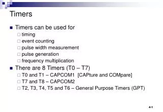
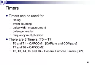
Timer.2 - Timers in ATmega16 • Many computer applications require accurate timing. Examples include • recording the time when an event occurs, • calculating the time difference between events, • performing tasks at specific or periodic times, • creating accurate time delays, • generating waveforms of certain shape, period, or duty cycle. Timers and PWM Lectures focus on using timers to perform time-related processing.
Timer terminology • Input Capture: • An input signal is connected to a pin, called input capture, of the timer. • When a preset event (rising edge, falling edge, change) occurs on this pin, the current timer value is stored in a register. • Output Compare: • A timer typically has a pin, called output compare. • When the timer reaches a preset value, the output compare pin can be automatically changed to logic 0 or logic 1.
Overview of Timers in ATmega16 • ATmega16 has three timers: Timer 0, Timer 1 and Timer 2. Each timer is associated with a counter and a clock signal. The counter is incremented by 1 in every clock cycle of the timer. • The clock signal of a timer can come from • the internal system clock or • an external clock source.
Overview of Timers in ATmega16 When the internal system clock is used, a prescaler can be applied to make the timer count at a slower rate. • Example: • Consider a system clock of 1Mhz (i.e. 1μs per cycle). • Suppose that a timer prescaler of 64 is used. • Then, timer will increment every 64μs.
Overview of Timers in ATmega16 Timer 1 has the most capability among the three timers.
Study plan • In previous Lecture , we focus on • operations of Timer 1, • using Timer 1 overflow interrupt, • using Timer 1 input capture interrupt, • measuring time, creating time delay, • measuring period/duty cycle of a signal, • information required for Lab 9. • In this Lecture, we will learn • using Timer 1 output compare interrupt, • generating PWM signals, • information required for Lab 3.
Timer 1: An overview • 16-bit counter. 10-bit prescaler: 8, 64, 256, and 1024 can trigger a timer overflow interrupt when counter reaches MAX. • can trigger an input capture interrupt when an event occurs on the input capture pin. • timer value is stored automatically in a register. • input capture pin for Timer 1 is ICP1 (D.6). • can trigger an output compare match interrupt when timer reaches a preset value. • There are two independent output compare channels A and B.
Timer 1: Block diagram External clock pin Current timer/counter value Output Compare pins Output Compare Registers Input Capture register Input Capture pin Timer/Counter Control Registers Not shown here: TIMSK and TIFR registers
Timer 1 ─ Relevant pins used in this lecture
Timer 1 ─ Five groups of registers 5) Output Compare Registers • OCR1A, OCR1B • To store the preset values for output compare. will be covered in PWM Lecture 1) Timer/Counter 1 • TCNT1 • 16-bit register that stores the current value of the timer. 2) Timer/Counter 1 Control Registers • TCCR1A and TCCR1B • To configure the operations of Timer 1. 3) Input Capture Register • ICR1 • to store timer value when an event occurs on input capture pin. 4) Interrupt registers • TIMSK to enable timer interrupts • TIFR to monitor status of timer interrupts.
Timer 1 ─ Five groups of registers We now study the important registers for Timer 1.
Timer.2.1 - Timer/Counter 1 Control Register A (TCCR1A) 6 3 5 7 4 1 2 0 COM1A1 COM1A0 COM1B1 COM1B0 FOC1A FOC1B WGM11 WGM10 Specify Waveform Generation Mode used with WGM13, WGM12 WGM13..WGM10 = 0000 for normal mode. 1 to force output compare on channel B 1 to force output compare on channel A Output compare mode for channel B Output compare mode for channel A
Timer.2.2 - Timer/Counter 1 Control Register B (TCCR1B) 6 3 5 7 4 1 2 0 ICNC1 ICES1 - WGM13 WGM12 CS12 CS11 CS10 clock select (next slide) select Waveform Generation Mode, used with WGM11, WGM10 WGM13..WGM10 = 0000 for normal mode. input capture edge select: 1 will select rising edge, 0 will select falling edge 1 to activate input capture noise canceller
Clock select For ATmega16, the internal clock is set by default at clkI/O = 1MHz. Timer 1 can use the internal or external clock. If using the internal clock, we can set Timer 1 to run 8, 64, 256, or 1024 times slower than the internal clock.
Timer.2.3 - Timer/Counter Interrupt Mask Register (TIMSK) 7 6 5 4 3 2 1 0 OCIE2 TOIE2 TICIE1 OCIE1A OCIE1B TOIE1 OCIE0 TOIE0 For Timer 0 Timer 1 Overflow Interrupt Enable Timer 1 Output Compare B Match Interrupt Enable: 1 to enable Timer 1 Output Compare A Match Interrupt Enable: 1 to enable Timer 1 Input Capture Interrupt Enable: 1 to enable For Timer 2
Timer.2.3 - Timer/Counter Interrupt Flag Register (TIFR) 6 3 5 7 4 1 2 0 OCF2 TOV2 ICF1 OCF1A OCF1B TOV1 OCF0 TOV0 For Timer 0 Timer 1 Overflow Interrupt Flag: set to 1 when overflow Timer 1 Output Compare B Match Flag: set to 1 when match Timer 1 Output Compare A Match Flag: set to 1 when match Timer 1 Input Capture Flag: set to 1 when capture event occurs For Timer 2 This register has flags that indicate when a timer interrupt occurs.
Timer.3 - Timer applications • In this section, we consider three applications of Timer 1. 1 Creating an accurate delay using timer overflow interrupt. 2 Measuring elapsed time between two events. 3 Measuring the period of a square signal using input capture interrupt.
Timer.3.1 - Creating an accurate delay Write a C program for ATmega16 to toggle PORTB every 2 seconds. It should use Timer 1 overflow interrupt to create delays of 2s each. • Analysis • Internal system clock: 1MHz. • With no prescaler, Timer 1 increments every 1 μs. • Timer 1 is 16-bit counter, so it will overflow every 216μs. • For a 2s delay, we need Timer 1 to overflow for 2s/216 μs = 31 times. • Coding • Write code to enable & intercept Timer 1 overflow interrupt. • Use interrupt handler to count the number of overflows. • When the number of overflows is 31, toggle port B.
Creating an accurate delay: timer_delay.c 1 2 #include <avr/io.h> #include <avr/interrupt.h> volatile int overflow_count; ISR(TIMER1_OVF_vect){ // handler for Timer1 overflow interrupt overflow_count++; // increment overflow count if (overflow_count >= 31){ // when 2s has passed overflow_count = 0; // start new count PORTB = ~PORTB; // toggle port B } } int main(void) { DDRB = 0xFF; // set port B for output PORTB = 0x00; // initial value of PORTB overflow_count = 0; // initialise overflow count TCCR1A = 0b00000000; // normal mode TCCR1B = 0b00000001; // no prescaler, internal clock TIMSK = 0b00000100; // enable Timer 1 overflow interrupt sei(); // enable interrupt subsystem globally while (1){;} // infinite loop return 0; } 4 3 5
Timer.3.2 - Measuring elapsed time • To measure time using Timer 1, we must keep track of both • the number of times that Timer 1 has overflowed: n • the current counter value: TCNT1 If we reset n and TCNT1 at the beginning of the interval, then the time elapse is (assuming no prescaler, 1MHz clock) t = n x 65536 + TCNT1 (μs) Timer Overflows TCNT1 n = 0 TCNT1 = 0 n 2 1 time interval t stop at timet2 start at time t1
Measuring elapsed time Use Timer 1 to measure the execution time of some custom C code. • Approach: • Clear Timer 1 when the code starts. • Record Timer 1 when the code finishes. • Also, use Timer 1 Overflow Interrupt to keep track of how many times it has overflowed.
Measuring elapsed time: measure_time.c #include <avr/io.h> #include <avr/interrupt.h> #include <inttypes.h> volatile uint32_t n; ISR(TIMER1_OVF_vect){ // handler for Timer1 overflow interrupt n++; // increment overflow count } int main(void) { inti, j; uint32_t elapse_time; // uint32_t is unsigned 32-bit integer data type TCCR1A = 0b00000000; // normal mode TCCR1B = 0b00000001; // no prescaler, internal clock TIMSK = 0b00000100; // enable Timer 1 overflow interrupt n = 0; // reset n TCNT1 = 0; // reset Timer 1 sei(); // enable interrupt subsystem globally // ----- start code -------------- for (i = 0; i < 100; i++) for (j = 0; j < 1000; j++){;} // ----- end code ----------------- elapse_time = n * 65536 + (uint32_t) TCNT1; cli(); // disable interrupt subsystem globally return 0; } any code
Timer.3.3 - Measuring period of a square signal Input capture interrupt is triggered. Read ICR1 register again. Input capture interrupt is triggered. Read ICR1 register. Use Timer 1 input capture interrupt to measure the period of a square wave. • Analysis: • The period of a square wave = the time difference between two consecutive rising edges. • Connect the square wave to input capture pin of Timer 1. • Configure input capture module to trigger on a rising edge. square waveform period
Measuring period of a square signal • Assumption: the input signal has a high frequency, hence timer overflow can be ignored. • Implementation: • Select timer operations: normal, no prescaler, internal clock 1MHz, noise canceller enabled, input capture for rising edges. TCCR1A = 0b00000000; TCCR1B = 0b00000001; • Enable input capture interrupt: TIMSK = 0b00100000;
measure_period.c #include <avr/io.h> #include <avr/interrupt.h> #include <inttypes.h> uint16_t period; // data type: unsigned 16-bit integer ISR(TIMER1_CAPT_vect){ // handler for Timer1 input capture interrupt period = ICR1; // period = value of Timer 1 stored in ICR1 TCNT1 = 0; // reset Timer 1 PORTB = ~(period >> 8); // display top 8-bit of period on PORT B } int main(void) { DDRB = 0xFF; // set port B for output TCCR1A = 0b00000000; // normal mode TCCR1B = 0b11000001; // no prescaler, rising edge, noise canceller TIMSK = 0b00100000; // enable Timer 1 input capture interrupt sei(); // enable interrupt subsystem globally while (1){;} // infinite loop return 0; }
Testing measure_period.c Write a C interrupt-driven program to toggle port B whenever a switch on the STK500 board is pressed. The program should use an external interrupt. • To test the code for measuring period: • Connect Input Capture pin (D.6) to square wave generator on WishMaker. • Connect GRD pin of Port D to GRD pin of WishMaker. • Connect Port B to LED connector. • Compile, download program. • Change frequency of square ware and observe output on LEDs. Video demo: measure_period.mp4
Extending measure_period.c • This example assumes no timer overflow between two rising edges of the square signal. In Lab, you are required to extend the code to measure the period for low-frequency signals. It is necessary to intercept timer overflow (see Examples in Timer Lecture). For testing, the measured period should be sent to PC via serial port.