Download
1 / 1
10 likes | 414 Views
Darcy Lambert Laura Peterson and Professor Piotr Decowski How accurately was electron beam polarization measured in the E158 experiment at SLAC? Measurements of Performance of the Detector Used in a Precise High energy Electron-Electron Scattering Experiment at SLAC

E N D
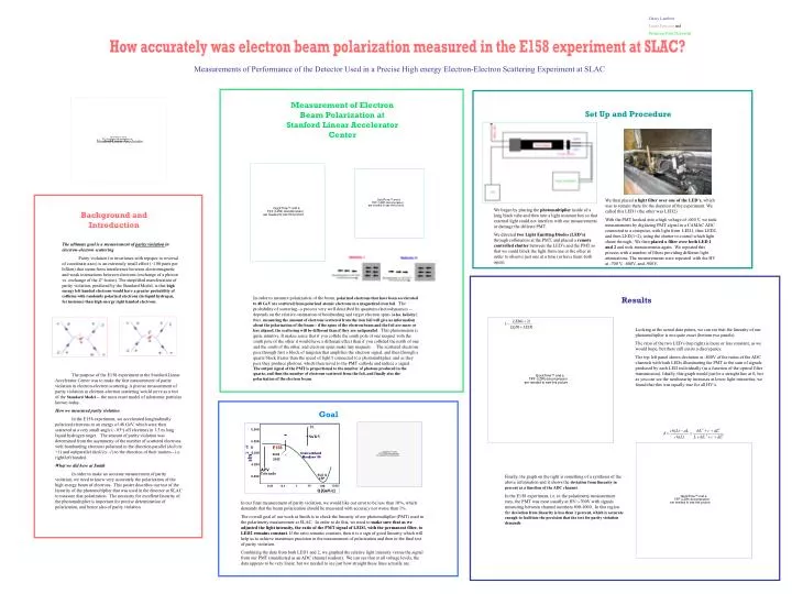
Darcy Lambert Laura Peterson and Professor Piotr Decowski How accurately was electron beam polarization measured in the E158 experiment at SLAC? Measurements of Performance of the Detector Used in a Precise High energy Electron-Electron Scattering Experiment at SLAC Measurement of Electron Beam Polarization at Stanford Linear Accelerator Center Set Up and Procedure Stanford Linear Accelerator We then placed a light filter over one of the LED’s, which was to remain there for the duration of the experiment. We called this LED1 (the other was LED2) With the PMT hooked into a high voltage of -600 V, we took measurements by digitizing PMT signal in a CAMAC ADC connected to a computer, with light from LED1, then LED2, and then LED(1+2), using the shutter to control which light shone through. We then placed a filter over both LED 1 and 2 and took measurements again. We repeated this process with a number of filters providing different light attenuations. The measurements were repeated with the HV at -700 V, -800V, and -900V. We began by placing the photomultiplier inside of a long black tube and then into a light resistant box so that external light could not interfere with our measurements or damage the delicate PMT. We directed two Light Emitting Diodes (LED’s) through collimators at the PMT, and placed a remote controlled shutter between the LED’s and the PMT so that we could block the light from one or the other in order to observe just one at a time (or have them both open). Background and Introduction The ultimate goal is a measurement of parity violation in electron-electron scattering Parity violation (or invariance with repspec to reversal of coordinate axes) is an extremely small effect (~100 parts per billion) that stems from interference between electromagnetic and weak interactions between electrons (exchange of a photon vs. exchange of the Zo boson). The simplified manifestation of parity violation, predicted by the Standard Model, is that high energy left handed electrons would have a greater probability of collision with randomly polarized electrons(in liquid hydrogen, for instance) than high energy right handed electrons. In order to measure polarization of the beam, polarized electrons that have been accelerated to 48 GeV are scattered from polarized atomic electrons in a magnetized iron foil. The probability of scattering--a process very well described by quantum electrodynamics -- depends on the relative orientation of bombarding and target electron spins (a.ka. helicity); thus, measuring the amount of electrons scattered from the iron foil will give us information about the polarization of the beam-- if the spins of the electron beam and the foil are more or less aligned, the scattering will be different than if they are antiparallel. This phenomenon is quite intuitive. It makes sense that if you collide the south pole of one magnet with the south pole of the other it would have a different effect than if you collided the north of one and the south of the other, and electron spins make tiny magnets. The scattered electrons pass through first a block of tungsten that amplifies the electron signal, and then through a quartz block (faster than the speed of light!) connected to a photomulitplier, and as they pass they produce photons, which then travel to the PMT cathode and induce a signal. The output signal of the PMT is proportional to the number of photons produced in the quartz, and thus the number of electrons scattered from the foil, and finally also the polarization of the electron beam. Results Looking at the actual data points, we can see that the linearity of our photomultiplier is not quite exact (bottom two panels). The ratio of the two LED’s (top right) is more or less constant, as we would hope, but there still exists a discrepancy. The top left panel shows deviation at -800V of the ratios of the ADC channels with both LEDs illuminating the PMT to the sum of signals produced by each LED individually (as a function of the optical filter transmission). Ideally, this graph would just be a straight line at 0, but as you can see the nonlinearity increases at lower light intensities, we found that this was equally true for all HV’s. The purpose of the E158 experiment at the Stanford Linear Accelerator Center was to make the first measurement of parity violation in electron-electron scattering. A precise measurement of parity violation in electron-electron scattering would serve as a test of the Standard Model -- the most exact model of subatomic particles known today. How we measured parity violation In the E158 experiment, we accelerated longitudinally polarized electrons to an energy of 48 GeV, which were then scattered at a very small angle (~.03o) off electrons in 1.5 m long liquid hydrogen target. The amount of parity violation was determined from the asymmetry of the number of scattered electrons with bombarding electrons polarized in the direction parallel (helicity +1) and antiparallel (helicity -1) to the direction of their motion-- i.e. right/left handed. What we did here at Smith In order to make an accurate measurement of parity violation, we need to know very accurately the polarization of the high energy beam of electrons. This poster describes our test of the linearity of the photomultiplier that was used in the detector at SLAC to measure that polarization. The necessity for excellent linearity of the photomultiplier is important for precise determination of polarization, and hence also of parity violation. Goal Finally, the graph on the right is something of a synthesis of the above information and it shows the deviation from linearity in percent as a function of the ADC channel. In the E158 experiment, i.e. in the polarimetry measurement runs, the PMT was most usually at HV=-700V with signals measuring between channel numbers 800-1000. In this region the deviation from linearity is less than 1 percent, which is accurate enough to facilitate the precision that the test for parity violation demands. In our final measurement of parity violation, we would like our error to be less than 10%, which demands that the beam polarization should be measured with accuracy not worse than 1%. The overall goal of our work at Smith is to check the linearity of our photomultiplier (PMT) used in the polarimetry measurement at SLAC. In order to do this, we need to make sure that as we adjusted the light intensity, the ratio of the PMT signal of LED1, with the permanent filter, to LED2 remains constant. If the ratio remains constant, then it is a sign of good linearity which will help us to achieve maximum precision in the measurement of polarization and then in the final test of parity violation. Combining the data from both LED1 and 2, we graphed the relative light intensity versus the signal from our PMT (manifested as an ADC channel readout). We can see that at all voltage levels, the data appears to be very linear, but we needed to see just how straight these lines actually are.