Download
1 / 32
340 likes | 828 Views
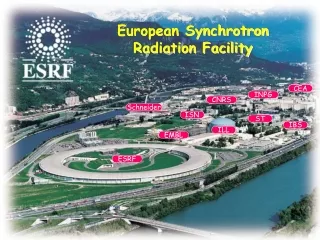
Synchrotron Radiation Sources and Optics. Grant Bunker Professor of Physics BCPS Department, IIT. topics. sources monochromators mirrors focussing. Requirements for Diffraction. Precise details depend on nature of sample Bragg’s law: n λ=2d sin(Θ)

E N D
Synchrotron Radiation Sources and Optics • Grant Bunker • Professor of Physics • BCPS Department, IIT
topics • sources • monochromators • mirrors • focussing
Requirements for Diffraction • Precise details depend on nature of sample • Bragg’s law: n λ=2d sin(Θ) • Collimated beam is needed to define Θ: • ΔΘ should be <reflection width or mosaic spread of sample • Monochromatic beam is needed to define λ; E= hc/λ (photons) • ΔE/E = - Δλ/λ; Bragg: Δλ/λ = cot(Θ) Δ Θ • MAD requires tunable beam, ΔE/E < 10-4 • Powders may benefit from larger ΔΘ • Laue experiments may require bandwidth of ~ 1KeV
Limitations of X-ray tubes • Fluorescence emission from anode that is induced by high energy electron impact produces characteristic x-ray fluorescence, superimposed on Bremsstrahlung continuum • lines are not (continuously) tunable • x-rays are emitted in all directions • need special optics to collect the X-rays and redirect them into roughly collimated beam
Why Synchrotron Radiation? • It’s far more intense (>106) than lab sources • Tunable energy • Naturally collimated in vertical plane - clean • well-matched to crystal monochromators • undulators produce pencil beam of x-rays • Brilliance is much greater than other sources • photons/sec/source size/angular divergence • Light comes in rapid pulses - useful for time resolution
Brilliance of X-ray Sources graphic courtesy of APS
Light Emission • Accelerating charged particles emit electromagnetic radiation • radio, microwave, infrared, visible, UV, X-rays, gammas • These are emitted in a dipole pattern • Not collimated - frequency is same as oscillation frequency - radio waves? No radiation alongacceleration vector
Relativity changes everything • When particles move at speeds close to the speed of light • it’s still a dipole pattern in their instantaneous rest frame • but in lab frame, radiation pattern tilts sharply into the forward direction “headlight effect” • Frequency of emitted light measured in lab frame is dramatically higher -> x-rays
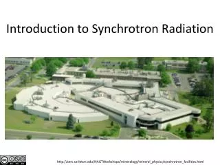
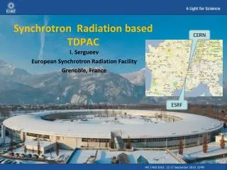
Our Friendly Neighborhood Synchrotron Source Advanced Photon Source Argonne, IL
Inside the APS: Linac Synchrotron Storage Ring Text Text Insertion Devices Beamlines!
Inside the ring • Electrons circulate very nearly at the speed of light (at the APS, only 1.5 m/s slower than c!). • Relativistic parameter γ=E/mc2 • Their paths are made to bend using dipole bend magnets. The beams are focussed with quadrupole and sextupole magnets • “insertion devices” (wigglers and undulators) can be placed in straight sections between dipole bend magnets
Synchrotron Radiation • Wherever the path of the electrons bends, their velocity vector changes • This acceleration causes them to produce electromagnetic radiation • In the lab rest frame, this produces a horizontal fan of x-rays that is highly collimated (to ΔΘ≈ 1/γ) in the vertical direction and extends to high energies • Energy is put back into electron beam by “surfing” through radio frequency (RF) cavities
Universal Flux Curvebend magnets & wigglers εc =19.5 KeV for APS dipole bend magnetsxt Text Text Synchrotron function g1(x) (solid) and simple approximation (dashes): f(x) = 1.8 x0.3 Exp(-x), where x=ε/εc. A more accurate approximation (not shown) is g1(x)=a*xbexp(-c x), with a=1.71857, b=0.281526, c=0.968375. The spectral photon flux (photons /sec/0.1% bandwidth (Δε/ε)/mA beam current/mrad) integrated over the full vertical opening angle is 1.256 *107γ g1[x], with γ=E/mc2 and εc =3hc γ3/(4πρ)
Insertion Devices • arrays of magnets of alternating polarity between which the beam travels • The alternating magnetic field causes the path of the electrons to wiggle back and forth • Acceleration causes emission of radiation at each pole (typically 50-100 poles) • Unlike bend magnets, ID properties can be chosen to optimize beam specifically for experiments • Two main types: Wigglers and Undulators Text
Wigglers vs Undulators • Wigglers cause the electron beam to oscillate with angular deviation that is large compared to 1/γ • Wiggler spectrum follows universal curve (like bend magnet), scaled by number of poles • Undulators use smaller deflections compared to 1/γ • Light emitted at each pole interferes with that emitted from others • Energy spectrum is bunched up into harmonics • Radiation pattern is a pencil of light in forward direction
X-ray Polarization • In the orbital plane, the radiation is nearly 100% linearly polarized • This can be used for polarized XAFS (x-ray linear dichroism) experiments on oriented specimens • Out of the orbital plane, bend magnet radiation has some degree of left/right circular polarization • Wiggler/undulator radiation is not circularly polarized (planar devices)
What beamlines do • Beamlines are complex instruments that prepare suitable x-ray beams for experiments, and protect the users against radiation exposure. • They combine x-ray optics, detector systems, computer interface electronics, sample handling/cooling, and computer hardware and software.
Typical Beamline Functions • Radiation shielding and safety interlock • Select/scan energies/wavelengths using monochromators • Focus the beams with x-ray mirrors, bent crystals, fresnel zone plates, or refractive optics • Define the beams with x-ray slits • Measure beam intensity and record diffraction patternwith suitable detectors • Electronics amplify signal and interface to the computers • Computer control and data acquisition system orchestrates motion of the monochromator and other optics, controls readout of detectors, and mediates remote control alignment of samples.
Crystallography Beamline Layout graphic courtesy of SER-CAT
Monochromators BioCAT ID-18 Design by Gerd Rosenbaum & Larry Rock
Heat load issues • Undulators pose special challenges for optics • high power density makes silicon at room temperature unsuitable (mostly): need higher thermal conductivity or lower thermal expansion coefficient • Cooling silicon to ~100K improves both properties • Diamonds are excellent thermal conductors and synthetic diamonds are suitable monochromator crystals
Mirror reflectivity vs absorptivity of surface coating Φ=Θ/Θc
Harmonics • Monochromators transmit not only the desired fundamental energy, but also some harmonics of that energy. Allowed harmonics for Si(111) include 333, 444, 555, 777… • These can be reduced by slightly misaligning “detuning” the second crystal using a piezoelectric transducer (“piezo”). Detuning reduces the harmonic content much more than the fundamental. • If a mirror follows the monochromator, its angle can be adjusted so that it reflects the fundamental, but does not reflect the harmonics. • We have developed devices called “Beam Cleaners” can be made to select particular energies
Focussing equations • Meridional focussing (typically, vertical mirror) • optic curved along beam direction • 2 /(R Sin(Θ)) =1/u+1/v • Sagittal focussing (typically, horizontal crystal or mirror) • optic curved perpendicular to beam direction • 2 Sin(Θ)/R=1/u+1/v • u,v are source to optic distance, optic to focus distance • R is local radius of curvature of optic • Kirkpatrick-Baez mirror or Toroidal mirror
Conclusion • We have covered sources, monochromators, mirrors, and focussing • In single crystal diffraction experiments, once a monochromatic beam is delivered to the sample, the goniometer and detector do most of the work. • In MAD experiments, it is necessary to measure the diffraction patterns at several relatively close energies, but the principles are the same • Other variants of diffraction (e.g. DAFS) require more sophisticated control system, but the principles are the same