Download
1 / 8
80 likes | 200 Views
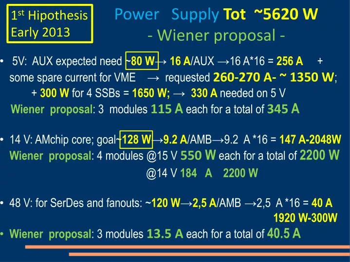
Power Supply Tot ~5620 W - Wiener proposal -. 1 st Hipothesis Early 2013. 5V: AUX expected need ~ 80 W → 16 A /AUX → 16 A*16 = 256 A + some spare current for VME → requested 260-270 A- ~ 1350 W ; + 300 W for 4 SSBs = 1650 W; → 330 A needed on 5 V

E N D
Power Supply Tot~5620 W - Wiener proposal - 1stHipothesis Early 2013 • 5V: AUX expected need ~80 W→16 A/AUX →16 A*16 = 256 A + some spare current for VME → requested 260-270 A- ~ 1350 W; • + 300 W for 4 SSBs = 1650 W; →330 A needed on 5 V • Wiener proposal: 3 modules 115 A each for a total of 345 A • 14 V: AMchip core; goal~128 W→9.2 A/AMB→9.2 A *16 = 147 A-2048W Wiener proposal: 4 modules @15 V 550 W each for a total of 2200 W • @14 V 184 A 2200 W • 48 V: for SerDes and fanouts: ~120 W→2,5 A/AMB →2,5 A *16 = 40 A • 1920 W-300W • Wiener proposal: 3 modules 13.5 A each for a total of 40.5 A
1stHipothesis early 2013 In summary: 10 module maximum in a Wiener box • 5V: 3 modules 115 A each for a total of 345A; Needed ~240 A • proposal: go down to 2 modules 230 A and integrate with 14 V • 14 V: 4 modules for a total of 184 A; Needed~147 A for Amchip core only; • use ex 3.3 V pins in J1 • proposal: go up to 5 modules 230 A and use it also in J0 for SSB and AUX • 48 V: 3 modules for a total of 40,5A; Needed ~40 A for AMB only – use V1,V2 pins in J1 • Why the proposal: more balanced currents between 5 V and 14 V; more redundancy on 14 V – • possible to balance AMB-SSB-AUX needs
Update -Option A Power needed/crate~5870 W Wiener: not standard 2ndHipothesis AUX-SSB 90 W • 5V: VME + SSB →SSB 90 W/board tot 360 W (70 A); • Wiener proposal: 1 module 115 A for a total of 575 W • 12 V: Amchip core + AUX board • AMchip core; goal~128 W→10.7 A/AMB→10.7 A *16 = 170, 7 A-2048W • AUX card; 90 W→7,5 A/AUX→7.5 A *16 = 120 A- 1440 W • Wiener proposal: 6 modules @12 V 600 W each for a total of 3500 W • @12 V 50 A each for a total of 300 A (3600 W) ??? • 48 V: for SerDes and fanouts: ~120 W→2,5 A/AMB →2,5 A *16 = 40 A • 1920 W • Wiener proposal: 3 modules 13.5 A each for a total of 40.5 A
Update -Option B Power needed/crate ~5870 W Wiener not standard 2ndHipothesis AUX-SSB 90 W • 5V: VME + SSB? →SSB 90 W/board tot 360 W (70 A); • Wiener proposal: 1 module 115 A for a total of 575 W • 12 V: Amchip core • AMchip core; goal~128 W→10.7 A/AMB→10.7 A *16 = 170, 7 A-2048W • Wiener proposal: 4 modules @12 V 600 W each for a total of 2400 W • @12 V 50 A each for a total of 200 A (2400 W) ??? • 48 V: for SerDes and fanouts: ~120 W→2,5 A/AMB →2,5 A *16 = 40 A • 1920 W-300W • AUX card; 90 W→1,875 A/AUX→1,875 A *16 = 30 A- 1440 W • Wiener proposal: 6 modules 13.5 A each for a total of 81 A
VME BACKPLANE NEW Proposal – end 2013 J1 J2 J0 - Vipa 2 pins on J1(3 A max)→ 48 V : Max 3 A/board, available to AMB only; 2,5 A/Amboard needed 5V in J1, J2 and J0 → 4+3+6 pins (19,5 A max): for SSB only (97 W max); VPC pins → 3(4,5 A max) for VME + extra support to SSB (22.5 W max); 12V in J1 → 10 pins ex 3.3 V, eventually also 1 extra pin at 12 V; They are connected together now for Amchip core only, 10 A * 16 =160 A in J1; For AUX allocated the J0→ 8 pins; Option A 12V: tot available current ~12 A → ~ 144 W/board Option B 48 V: tot available current ~12 A → ~ 576 W/board max power
IF the hypothesis are NOT respected (2 W/ 128 kpattern & 90 W/FPGA board, SSB or AUX) We need 4 more crates and less boards/crate
RACK OPTIONS Green ~cable length assuming Bins have Connection tools on top & PS output on top & bottom CAEN IDEA 1 single PS For 2 crates In the middle AGOSTINO’S STANDARD – Wiener PS and FAN
UNCERTAINTIES on made IPOTHESIS Will AMCHIP core consumption be < 1 W /64 kpatterns ?? Will AUX board consumption be ~ 90 W ?? Proposal: let’s use what we have for 2015 as much as possible, let’s buy new stuff when uncertainties above are clarified. RACK will be defined at that moment.