Vision System in real-time tracking
210 likes | 423 Views
Vision System in real-time tracking. 2002. 8. 12 MAI LAB Ryu Mi Wyun. Real-time vision-based tracking control of an unmanned vehicle. Kok-Meng LEE, Zhi Zhou, Robert Blenis and Erik Blasch* *The George W. Woodruff School of Mechanical Engineering,

Vision System in real-time tracking
E N D
Presentation Transcript
Vision System in real-time tracking 2002. 8. 12 MAI LAB Ryu Mi Wyun
Real-time vision-based tracking control of an unmanned vehicle Kok-Meng LEE, Zhi Zhou, Robert Blenis and Erik Blasch* *The George W. Woodruff School of Mechanical Engineering, Georgia Institute of Technology, Atlanta, GA 30332-0405, USA Mechatronics Vol.5, No. 8 (1995) 973 - 997
Contents • Introduction • Integrated vision-based control • Dynamic modeling and control strategy • Integrated vision-based tracking control system • Experimental investigation • Conclusions
Introduction (1/2) Increased Demand for Autonomous Vehicles Unattended Factories Material Handling Warehouse Operation Hazardous Environment Requires real-time position and/or velocity feedback Using Machine Vision to provide the feedback info. Advances In Manufacturing Automation
Introduction (2/2) Target - Space Drive - Space Vision system • where the vehicle is located and oriented • where the vehicle is controlled, with an implementation of a path planning mechanism • Major difficulties • Slow and/or expensive visual feedback • Complicated dynamics and control with constraints in ‘target space’ • The development of a practical method for implementing real-time vision based control of autonomous vehicles.
Integrated vision-based control - Idea • Vision-based vehicle control systems • Spaced-fixed vision systems : range of motion is restricted/ more than one vision system is required • On-the-Vehicle (On-board) vision systems • Takes pictures periodically while moving • Captures the patterns within its fields of view • Stores and analyzes the images • Returns the vehicle’s locations
Integrated vision-based control – Fiducial patterns • Landmarks to determine the vehicle’s location • using a feature set • made of retro-reflective material to eliminate noise • An illustrative example • , , • Two distinct distances between two elements : • Pattern orientation :
Integrated vision-based control – Pattern recognition • Real world Coordinate • Image Coordinate
Dynamic modeling and control strategy Obtain the complete set of dynamic models Propose a path planning mechanism Outline the control strategy development • Three-wheeled vehicle • Vehicle is modeled as a rectangular plate of dimensions • The axes of the driving motor shafts are perfectly aligned / • are located directly below the transversal axis of the vehicle
Dynamic modeling and control strategy • The torques applied at the wheels • Masses of the wheel and the vehicle • The radius of the rear wheels • Vehicle Dynamics : using Lagrangian formulation position of the center of gravity of the vehicle, orientation of the axis .. Equations of motion for the vehicle are..
Dynamic modeling and control strategy • Path Planning : Implementation of simplified controller design
Dynamic modeling and control strategy* • Utilizing the visual feedback and modern digital control technology • Control functions will be implemented using DSP and/or computers • - design the controllers in the discrete-time domain • Digital tracking controller : Discretize state-space representation of the motor dynamics
Dynamic modeling and control strategy* • Utilizing the visual feedback and modern digital control technology • Control functions will be implemented using DSP and/or computers • - design the controllers in the discrete-time domain • Digital tracking controller : Discretize state-space representation of the motor dynamics • Regulator with reduced-order observer : Obtain the specified time response of the system
Dynamic modeling and control strategy* • Utilizing the visual feedback and modern digital control technology • Control functions will be implemented using DSP and/or computers • - design the controllers in the discrete-time domain • Digital tracking controller : Discretize state-space representation of the motor dynamics • Regulator with reduced-order observer : Obtain the specified time response of the system • Digital tracking filter : To follow an arbitrary desired time-varying trajectory
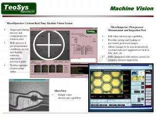
Integrated vision-based tracking control system • Laboratory prototype system • RS170-based systems • : Require pixel data to be stored in a video buffer • : Increased time and require video buffer size • FIVS – Providing the feedback information • : integrates imaging sensors, control, illumination, signal processing and data communication • : By directly transferring the A/D converter output to the DSP
Integrated vision-based tracking control system • ViTra (Vision-based Tracking system) • : Three wheel configuration with two rear driving wheels & ball-joint-like front wheel • : Rear wheels are geared to two D.C motors • Using the two motors • : reduces the backlash, friction and inertia.. • Ball-joint-like front wheel • : to maneuver in all directions without slip • ViTra integrates the three-wheeled autonomous vehicle, an on-board FIVS, a ceiling fiducial board, a DSP board with A/D and D/A converters, and an Intel 486 as central computer
Experimental investigation • 30 Patterns are placed 9.75 ft above the CCD lens • For different vehicle positions and orientations around a predetermined trajectory.
Experimental investigation • Fig.11-12 give the corresponding plots. • Slightly off from the known positions. • - average position deviation from the true position is 2.92 and 2.63 in. • Due to the level of the CCD lens and the lighting conditions etc.
Experimental investigation • Desired circular path with radius of 20 in. • A number of tests / Two typical paths are recorded. • Overall real paths follow the desired ones. • Some data points far from desired paths • - mismatch of the FIVS update rate & moving speed • - can be reduced by optimizing the pattern recognition • Reducing the trajectory discrepancy - unmodeled friction - ceiling board not perfectly leveled - approximation in path planning
Conclusions • ViTra uses a DSP-based flexible integrated vision system(FIVS) : low cost, computational efficiency, flexibility.. • Using fiducial patterns and corresponding pattern recognition • Can use the digital controllers and observer to enhance the performance • Sample circular trajectory tracking experiments illustrated the possibility Optimizing the fiducial patterns, Conducting various trajectory tracking tests