Download
1 / 18
250 likes | 768 Views
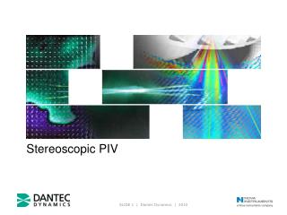
Stereoscopic Particle Image Velocimetry. Stereoscopic PIV. Need for Stereoscopic Measurements Most flows are three-dimensional in nature Need simultaneous measurement of the three orthogonal components 2D flow measurements using a Single camera Edges of the images are viewed obliquely

E N D
Stereoscopic PIV Need for Stereoscopic Measurements • Most flows are three-dimensional in nature • Need simultaneous measurement of the three orthogonal components • 2D flow measurements using a Single camera • Edges of the images are viewed obliquely • Out-of-plane motion “appears” to be in-plane motion • Errors due to these need to be corrected • Stereoscopic measurement eliminates these errors
Stereoscopic Technique • View the light sheet from two perspectives • Two cameras set up at different angles to illuminated plane • Each camera captures a pair of images • 2D image displacements for each camera image field • 3D displacement obtained from the two 2D displacements • Calibration or Mapping function generation • imaging point markers in the flow using both cameras • calibration grid with equally spaced markers used • Effect of window refraction and distortion accounted for • Mapping function generates • a one-to-one correspondence between marker positions and their image locations in the camera
Particle Image Velocimetry3 Component measurements Three Component PIV Measurements Measurement of 3 components of velocity simultaneously Illumination : using a light sheet 3 components of measurements in a plane
System Components • PIV laser and light sheet optics • Two POWERVIEW (or PIVCAM) cameras, lenses • Mounting fixture for the Scheimpflüg configuration • Two high speed camera interfaces • Stereoscopic camera alignment mount • Dual-plane Dual-sided (DPDS) target plate • LaserPulse Synchronizer • Stereoscopic INSIGHT software package • includes Tecplot package
Scheimpflüg Stereoscopic Arrangements back-scatter Measurement plane parallel to the bisector of the camera axes side-scatter forward-scatter
Scheimpflüg Stereoscopic Arrangement Out of Focus: in front of plane of focus Out of Focus: behind plane of focus Plane of Focus • Only Particles in the light sheet can be captured by the camera • The plane of focus is parallel to the sensing array • Portions of light sheet in front of and behind the plane of focus are out of focus Point of Focus Camera Lens CCD Array
Scheimpflüg Stereoscopic Arrangement Object plane (Light sheet) Plane of Focus Scheimpflüg Condition Lens principal plane Image plane Axis of Sensing Array Axis of Lens By rotating the sensing array with respect to the lens plane most of the objective plane can be focused
Scheimpflüg Stereoscopic Arrangement Object plane (Light sheet) Combine for a 3D Vector Left Camera View Right Camera View
Velocity vector in the light sheet xi = (x, y, z) Dx Laser light sheet A B Z d0 xf = (x + Dx, y + Dy, z + Dz) Y - axis normal to the plane of the paper d1 Xf Image plane Xi DX
3-D Displacements in the flow DXleft= Dxfluid(dXleft/dxfluid)+ Dyfluid(dXleft/dyfluid)+ Dzfluid(dXleft/dzfluid) DYleft = Dxfluid(dYleft/dxfluid)+ Dyfluid(dYleft/dyfluid)+ Dzfluid(dYleft/dzfluid) DXright = Dxfluid(dXright/dxfluid) + Dyfluid(dXright/dyfluid)+ Dzfluid(dXright/dzfluid) DYright= Dxfluid(dYright/dxfluid) + Dyfluid(dYright/dyfluid)+ Dzfluid(dYright/dzfluid) DX, DY are the measured image displacements - Dxleft corresponds to the image displacement in the left camera Dx, Dy and Dz are the particle displacements in the flow
Perspective effect due to camera tilt B A A B A B A B A B B A Right camera image of grid Regular grid in fluid Left camera image of grid
Stereoscopic technique - Calibration • Registration of the two cameras - align to view the same region • Distortion correction due to different media • Generates mapping function to map the vectors in the camera plane back to the object plane Calibration target Refracting wall Image recording plane Camera 2 Image recording plane Camera 1
Mapping function generationCalibration • Use rectangular grid of dots as calibration plate • Plate with grid markings • Dual-Plane Dual-Sided (DPDS)Target • Introduced by TSI • No need to traverse • Plate with grid markings in multiple planes on both sides of the plate • Calibration grid defines the coordinate system • Align the calibration plate with the light sheet DPDS Target
Calibration TargetDual-plane target Image of the target from the right camera Image of the target from the left camera
Remote control for PIV systems • Remote Scheimpflug control • Remote focusing • Remote aperture control • Used for • Underwater applications, Large tunnels • Facilities where remote access is needed
Guidelines for good Results • Interrogation spot size small enough so that one vector correctly describes the flow within that region • velocity gradient within the region is negligible • Three or more particle pairs per interrogation spot • improvement in accuracy is small for cases for more than 5 pairs of images • Max. in-plane displacement • < 1/4 of interrogation spot size • Min. in-plane displacement • could be zero • Maximum out of plane displacement • Less than ¼ of light sheet thickness