Download
1 / 56
560 likes | 588 Views
Frequency Domain Filtering. CS474/674 - Prof. Bebis Sections 4.7, 4.8, 4.9, 4.10. Frequency Domain Methods. Frequency Domain. Spatial Domain. Major filter categories. Typically, filters are classified based on their properties in the frequency domain: (1) Low-pass (2) High-pass

E N D
Frequency Domain Filtering CS474/674 - Prof. Bebis Sections 4.7, 4.8, 4.9, 4.10
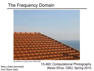
Frequency Domain Methods Frequency Domain Spatial Domain
Major filter categories • Typically, filters are classified based on their properties in the frequency domain: (1) Low-pass (2) High-pass (3) Band-pass (4) Band-stop
Example Original signal Low-pass filtered High-pass filtered Band-pass filtered Band-stop filtered
frequency domain Low-pass filters(i.e., smoothing filters) • Preserve low frequencies - useful for removing details and noise suppression. Example:
frequency domain High-pass filters(i.e., sharpening filters) • Preserves high frequencies - useful for highlighting details. Example:
frequency domain Band-pass filters • Preserves frequencies within a certain band. Example:
Band-stop filters • Removes frequencies within a certain band. Band-stop Band-pass
Frequency Domain Methods complex multiplication using real and imaginary parts Case 1: H(u,v) is specified in the frequency domain. Case 2: h(x,y) is specified in the spatial domain.
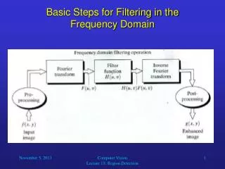
Frequency domain filtering: steps (note that P and Q must be powers of 2 to use FFT) F(u,v) = R(u,v) + jI(u,v)
Frequency domain filtering: steps (cont’d) (Case 1) complex multiplication G(u,v)= F(u,v)H(u,v) = H(u,v) R(u,v) + jH(u,v)I(u,v)
Example fp(x,y) f(x,y) fp(x,y)(-1)x+y F(u,v) G(u,v)=F(u,v)H(u,v) H(u,v) - centered g(x,y) gp(x,y)
(Case 2) h(x,y) specified in spatial domain • If h(x,y) is given in the spatial domain, H(u,v) can be generated as follows: • Form hp(x,y) by padding with zeroes. 2. Multiply by (-1)x+y to center its spectrum. 3. Compute its DFT to obtain H(u,v)
Example: h(x,y) is specified in the spatial domain 600 x 600 frequency spatial Sobel 602 x 602 frequency
Results of Filtering in the Spatial and Frequency Domains frequency domain filtering spatial domain filtering
Very Important: Preserving even/odd symmetrywhen padding with zeroes Sobel • Since h(x,y) is real and odd, H(u,v) should be imaginary and odd • We need to explicitly preserve odd symmetry of h(x,y) when padding with zeroes!
Important: Preserving even/odd symmetrywhen padding with zeroes (cont’d) Examples of 6 x 6 paddings: g(x,y)= -g(6-x,6-y) g(x,y) ≠ -g(6-x,6-y) 0 1 2 3 4 5 0 1 2 3 4 5 0 0 0 0 0 0 0 0 0 0 0 0 0 0 -1 0 1 0 0 0 -2 0 2 0 0 0 -1 0 1 0 0 0 0 0 0 0 0 0 0 0 0 0 0 0 0 0 0 0 0 -1 0 1 0 0 0 -2 0 2 0 0 0 -1 0 1 0 0 0 0 0 0 0 0 0 1 2 3 4 5 0 1 2 3 4 5 Sobel g(2,3)=-g(4,3) g(1,3) ≠ -g(5,3) (read details on pages 290-291 and 318-319)
Low Pass (LP) Filters • Ideal low-pass filter (ILPF) • Butterworth low-pass filter (BLPF) • Gaussian low-pass filter (GLPF)
Low-pass (LP) filtering • Preserves low frequencies, attenuates high frequencies. Ideal D0: cut-off frequency – user specified
Lowpass (LP) filtering (cont’d) • In 2D, the cutoff frequency is specified by the radius of a circle. Ideal
Choosing D0 • Most frequencies are concentrated around the center of the spectrum. • Consider a circle centered at point (N/2, N/2) in the frequency domain. • Choose the radius by specifying the percentage of total power to be preserved. e.g., preserve 80% of total power
Choosing D0 (cont’d) • Examples: r=8 (90% power) r=18 (93% power) original r: radius r=43 (95%) r=78 (99%) r=152 (99.5%)
Why LP perform smoothing? spatial domain freq. domain sinc * =
How does D0 control smoothing? (cont’d) • D0 controls the amount of blurring r=78 (99%) r=8 (90%)
Ringing Effect • Sharp cutoff frequencies produce an overshoot of image features whose frequency is close to the cutoff frequencies (ringing effect). h=f*g
Avoiding Ringing Effect • Attenuate higher frequencies smoothly. Ideal In practice D0: cut-off frequency – user specified
Butterworth LP filter (BLPF) n=1 n=4 n=16
Spatial Representation of BLPFs n=1 n=2 n=5 n=20
Comparison: Ideal LP and BLPF BLPF ILPF D0=10, 30, 60, 160, 460 D0=10, 30, 60, 160, 460 n=2
Gaussian: Frequency – Spatial Domains spatial domain frequency domain
Example 2: smoothing by GLPF D0=100 D0=80
High Pass (LP) Filters • Ideal high-pass filter (IHPF) • Butterworth high-pass filter (BHPF) • Gaussian high-pass filter (GHPF) • Difference of Gaussians • Unsharp Masking and High Boost filtering
High-pass filtering • Preserves high frequencies, attenuates low frequencies. H(u)
High-Pass filtering (cont’d) • A high-pass filter can be obtained from a low-pass filter: = 1 - D0
Butterworth high pass filter (BHPF) • In practice, we use filters that attenuate low frequencies smoothly (e.g., Butterworth HP filter) less ringing effect 1 -
Gaussian HP filter GHPF BHPF
Spatial Representation of High-pass Filters IHPF BHPF GHPF
Comparison: IHPF and BHPF IHPF D0=30,60,160 D0=30,60,160 n=2 BHPF
Comparison: BHPF and GHPF D0=30,60,160 BHPF n=2 D0=30,60,160 GHPF
Example: High-pass Filteringfor Fingerprint Image Enhancement BHPF (order 4 with a cutoff frequency 50)
Difference of Gaussians (DoG) filter Approximates the Laplacian This is a high-pass filter!
Highboost Filtering (revisited) Unsharp Masking: Highboost filtering: (previous formulation) Highboost filtering: (textbook’s formulation)
Highboost Filtering (revisited) FT Highboost Filter
Highboost and High-Frequency-Emphasis Filters 1+k k1+k2 1 k1 High-emphasis Highboost
Example GHPF D0=40 High-emphasis High-emphasis and hist. equal. High-Frequency Emphasis filtering Using Gaussian filter k1=0.5, k2=0.75
Homomorphic filtering • Can be used to remove shading effects in an image (i.e., due to uneven illumination) • Enhance high frequencies. • Attenuate low frequencies but preserve fine detail.
Homomorphic Filtering (cont’d) • Consider the following model of image formation: • Illumination i(x,y) varies slowly and affects low frequencies mostly. • Reflection r(x,y) varies faster and affects high frequencies mostly. i(x,y): illumination component r(x,y): reflection component
How are frequencies mixed together? • Low frequencies from i(x,y) and high frequencies from r(x,y) are convolved together. • When applying filtering, it is difficult to handle low/high frequencies separately.