Download
1 / 36
420 likes | 542 Views
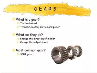
Milling Machines : Gear & Gear Cutting. By: Gp Capt Dr. Hamidullah Khan Niazi. Gears. Gears are used to transmit power from one shaft to another by means of successively engaging teeth

E N D
Milling Machines : Gear & Gear Cutting By: GpCapt Dr. Hamidullah Khan Niazi
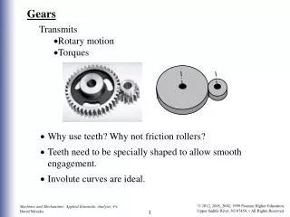
Gears Gears are used to transmit power from one shaft to another by means of successively engaging teeth They are used in place of belt drives and other forms of friction drives when exact speed ratios and power transmission must be maintained. Gears may also be used to increase or decrease the speed of the driven shaft, thus decreasing or increasing the torque of the driven member.
Terminology - spur gears • Diametral pitch (d p )...... The number of teeth per one inch of pitch circle diameter. • Module. (m) ...... The length, in mm, of the pitch circle diameter per tooth. • Circular pitch (p)...... The distance between adjacent teeth measured along the are at the pitch circle diameter • Addendum ( h a )...... The height of the tooth above the pitch circle diameter. • Centre distance (a)...... The distance between the axes of two gears in mesh. • Circular tooth thickness (ctt)...... The width of a tooth measured along the are at the pitch circle diameter. • Dedendum ( h f )...... The depth of the tooth below the pitch circle diameter. • Outside diameter ( D o )...... The outside diameter of the gear. • Base Circle diameter ( D b ) ...... The diameter on which the involute teeth profile is based. • Pitch circle dia ( p ) ...... The diameter of the pitch circle. • Pitch point...... The point at which the pitch circle diameters of two gears in mesh coincide. • Pitch to back...... The distance on a rack between the pitch circle diameter line and the rear face of the rack. • Pressure angle ...... The angle between the tooth profile at the pitch circle diameter and a radial line passing through the same point. • Whole depth...... The total depth of the space between adjacent teeth.
BACKLASH (B) is the amount by which the width of a tooth space exceeds the thickness of the engaging tooth on the pitch circles. As actually indicated by measuring devices, backlash may be determined variously in the transverse, normal, or axial-planes, and either in the direction of the pitch circles or on the line of action. Such measurements should be corrected to corresponding values on transverse pitch circles for general comparisons
Pressure Angle • Pressure angle is in general the angle at a pitch point between the line of pressure which is normal to the tooth surface, and the plane tangent to the pitch surface. The pressure angle gives the direction of the normal to the tooth profile. The pressure angle is equal to the profile angle at the standard pitch circle and can be termed the “standard” pressure angle at that point. Standard values include 14.5, 20 and 25 degrees. • Smaller pressure angles correlate with weaker teeth. To run gears together properly one must match pressure angles
The lines normal to the point of contact of the gears always intersects the centre line joining the gear centres at one point called the pitch point. For each gear the circle passing through the pitch point is called the pitch circle. The gear ratio is proportional to the diameters of the two pitch circles. For metric gears (as adopted by most of the worlds nations) the gear proportions are based on the module. • m = (Pitch Circle Diameter(mm)) / (Number of teeth on gear). • In the USA the module is not used and instead the Diametric Pitch d pis used • d p = (Number of Teeth) / Diametrical Pitch (inches)
Types of Gears • Spur gears are generally used to transmit power between two parallel shafts. The teeth on these gears are straight and parallel to the shafts to which they are attached. • When two gears of different sizes are in mesh, the larger is called the gear, while the smaller is called the pinion. Spur gears are used where slow- to moderate-speed drives are required.
Internal gears • Internal gears are used where the shafts are parallel and the centers must be closer together than could be achieved with spur or helical gearing. This arrangement provides for a stronger drive, since there is a greater area of contact than with the conventional gear drive. It also provides speed reductions. • Internal gears are used on heavy-duty tractors where much torque is required
Helical gears • Helical gears are used to connect parallel shafts or shafts that are at an angle. • Because of the progressive rather than intermittent action of the teeth, helical gears run more smoothly and quietly than spur gears. • Since there is more than one tooth in engagement at any one time, helical gears are stronger than spur gears of the same size and pitch. • However, special bearings (thrust bearings) are often required on shafts to overcome the end thrust produced by these gears as they turn.
On most installations where it is necessary to overcome end thrust, herringbone gears are used. This type of gear resembles two helical gears placed side by side, with one-half having a left-hand helix and the other half a right-hand helix. These gears have a smooth, continuous action and eliminate the need for thrust bearings.
When two shafts are located at an angle, with their axial lines intersecting at 90°, power is generally transmitted by means of bevel gears
When the shafts are at right angles and the gears are of the same size, they are called miter gears
However, it is not necessary that the shafts be only at right angles in order to transmit power. If the axes of the shafts intersect at any angle other than 90°, the gears are known as angular bevel gears
Modified bevel gears having helical teeth are known as hypoid gears (Fig. 69-5d). The shafts of these gears, although at right anglesare not in the same plane and, therefore, do not intersect. Hypoid gears are used in automobile drives e.g in differential of automobiles.
Worm & Worm Wheel • When shafts are at right angles and considerable reduction in speed is required, a worm and worm gear (Fig. 69-6) may be used. The worm, which meshes with the worm gear, may be single- or multiple-start thread. A worm with a double-start thread will revolve the worm gear twice as fast as a worm with a single-start thread and the same pitch. A worm wheel can also ensure a big speed reduction
Worm Gear (Cont’d) • The gear ratio of a worm gear is worked out through the following formula: number of teeth on wormwheel number of teeth on worm The worm acts as a single toothed gear so the ratio is; number of teeth on wormwheel 1 EXAMPLE: If the wormwheel has 60 teeth so gear ratio is :601 & (Rotary velocity is also reduced by 60:1) Quite simply, this means a worm gear reduces the speed of the spur gear by sixty times. If you need a gear system whereby the speed is reduced by a considerable amount - a worm and wormwheel are worth considering.
When it is necessary to convert rotary motion to linear motion, a rack and pinion (Fig. 69-7) may be used. The rack, which is actually a straight or flat gear, may have straight teeth to mesh with a spur gear, or angular teeth to mesh with a helical gear.
Smaller gears at the back are driven round, in turn driving round the back wheel. As the back wheel turns the bicycle moves forwards. Gears driven by chains are used in machinery, motorcycles, in car engines and have many more applications.
Gear Train of Spur Gear Gear ‘A’ is called the ‘driver’ Gear ‘B’ is called the ‘driven’ gear. Gear B Gear A Gear ‘A’ has 30 teeth and gear ‘B’ has 20 teeth. If gear ‘A’ turns one revolution, how many times will gear ‘B’ turn ? When gear 'A' completes one revolution gear 'B' turns 1.5 revolutions (1½ times)
Bicycles normally have a large gear wheel which has a pedal attached and a selection of gear wheels of different sizes, on the back wheel. When the pedal is revolved the chain pulls round the gear wheels at the back. Look at the gear wheel with the pedal attached and compare it in size to the gear wheels in the centre of the back wheel. What do you notice about them? Smaller gears at the back are driven round, in turn driving round the back wheel. As the back wheel turns the bicycle moves forwards. Gears driven by chains are used in machinery, motorcycles, in car engines and have many more applications.
Gear Train with Three Gears Q The diagram below shows a gear train composed of three gears. Gear A revolves at 60 revs/min in a clockwise direction. (a) What is the output in revolutions per minute at Gear C? (b) In what direction does Gear C revolve ? (a) First work out the speed at Gear B. (Remember B is larger than A therefore, B outputs less revs/min and is slower) Next, take B and C. C is smaller, therefore, revs/minute will increase and rotation will be faster. (b) What direction does C revolve ? A is clockwise, B consequently is anti-clockwise and C is therefore clockwise.
Compound Gear Example Q This is an example of a “compound gear train”. Gear A rotates in a clockwise direction at 30 revs/min. What is the output in revs/min at D and what is the direction of rotation ? First find revs/min at B; B is smaller therefore it rotates faster and revs/min increase. C is fixed to B and therefore, rotates at the same speed. 90 REVS/MIN at C Next find revs/min at D D is smaller than C, therefore rotates faster (increased revs/min). A revolves in a clockwise direction, B is therefore anti-clockwise, C is fixed to B and is also anti-clockwise, which means D revolves in a clockwise direction.