Download
1 / 18
210 likes | 399 Views
Chapter 2 A Loop in the Pattern. Designing the Main Loop and Timing. Checklist. The following tools will be used throughout the course: MPLAB X, Integrated Development Environment (v1.8 or later, free) MPLAB XC16, C compiler (v1.11 or later, free)

E N D
Chapter 2 A Loop in the Pattern Designing the Main Loop and Timing
Checklist The following tools will be used throughout the course: • MPLAB X, Integrated Development Environment (v1.8 or later, free) • MPLAB XC16, C compiler (v1.11 or later, free) The following pieces of documentation will be used during this lesson: • PIC24FJ128GA010 Datasheet –DS39747 (latest rev.) • PIC24 Family Reference Manual - Section 14. Timers Make sure they are available and/or installed and ready to use on your computer. You can download them from Microchip web site at: http://www.microchip.com/mplabx And http://www.microchip.com/xc16
A New Project • Use the New Project wizard to create a new project • Call it: “2-ALoopInThePattern” • Use the New File wizard to create a new source file • Call it: Loop.c /* * File: Loop.c * Author: your name here * * Created current date here */ #include <xc.h> int main( void) { return 0; } But you can also use the form: void main( void) { // no return required } Or simply: main() { }
“while” Loops • In C there are several ways to design a loop. The first we are going to explore is the “while” loop: while ( x) { // your code here… } • Where ( X) is a logical expression • false is represented as the integer zero • true is represented by any integer exceptzero
Logical Operators • || the logic OR operator, • && the logic AND operator, • ! the logic NOT operator • These operators consider their operands as logical (Boolean) values using the rule mentioned above, and they return a logical value. • Here are some trivial examples, assuming: • a = 17 • b = 1 • ( a || b) is true, • ( a && b) is true • ( !a) is false • In other words, they are both “true”
Comparison Operators • There are, then, a number of operators that compare numbers (integers of any kind and floating point values, too) and return logic values. • They are: • == the equal-to operator, • != the NOT-equal to operator. • > the greater-than operator. • >= the greater-or-equal to operator. • < the less-than operator. • <= the less-or-equal to operator. • Here are some examples, assuming: • a = 10 • ( a > 1) is true • (-a >= 0) is false • ( a == 17) is false • ( a != 3) is true Composed of two equal signs to distinguish it from the assignment operator ‘=‘ we used in the previous lesson.
Curious Cases while ( 0) { // your code here… } while ( 1) { // your code here… } Will never execute this code! Will execute this code for ever!
Writing a Main Loop • It is time to add a few new lines of code to the ‘loop.c’ source file and put the whileloop to good use. main() { // init control registers TRISA = 0xff00; // all PORTA as output // main application loop while( 1) { PORTA = 0xff; PORTA = 0; } // main loop } // main
Not so fast, please! • Run > Run Program from the main menu. • MPLAB X will now recompile the program for immediate execution. It will be downloaded into the PIC24 flash memory and execution will start immediately • NOTE: When in run mode, there is no animated icon and MPLAB X seems inactive, but the target PIC24 is alive and executing continuously the application at full speed • Warning: You will not be able to see any flashing of the LED bar! • This is due to a limitation of our human eyes. • The PIC24 is actually turning the LEDs on and off but, assuming our default configuration of the main oscillator (32MHz), this is happening at the rate of several million times per second!
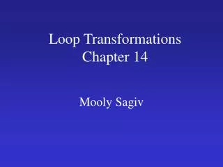
Using a Timer • Timer1 Block Diagram:
Configuring Timer1: T1CON • Use the following basic configuration: • Activate Timer1: TON = 1 • Use the MCU clock as the source (Fosc/2): TCS = 0 • Set the prescaler to the maximum value (1:256): TCKPS = 11 • The input gating and synchronization functions are not required, since we use the MCU internal clock directly as the timer clock: TGATE = 0, TSYNC = 0 • Do not worry about the behavior in IDLE mode, for now: TSIDL = 0 (default) • Once we assemble all the bits into a single 16-bit binary value, we get: • T1CON = 0b1000000000110000; • Or in a more compact hexadecimal notation: • T1CON = 0x8030;
A Timed Loop #include <config.h> #define DELAY 16000 main() { // init control registers TRISA = 0xff00; // all PORTA as output T1CON = 0x8030; // TMR1 on, prescale 1:256 Tclk/2 // main application loop while( 1) { //1. turn pin 0-7 on and wait for 1/4 of a second PORTA = 0xff; TMR1 = 0; while ( TMR1 < DELAY) { } // 2. turn all pin off and wait for a 1/4 of a second PORTA = 0; TMR1 = 0; while ( TMR1 < DELAY) { } } // main loop } // main
Notes for Assembly Experts • Logic vs. Binary operators in C: • Binary logic operators take pairs of bits from each operand and compute the result according to the defined table of truth. • Logicoperators, look at each operand (independently of the number of bits used) as a single Boolean value. • Example on byte sized operands: 11110101 11110101 (true) binary OR 00001000 logical OR00001000 (true) -------- -------- gives 11111101 gives 00000001 (true)
Notes for PICmicro Experts • Difference between 8-bit PICmicros and the PIC24: • There is no Timer0 • All timers are 16-bit wide. • Each timer has a 16-bit period registers (PR). • A new 32-bit mode timer-pairing mechanism is available for Timer2/3 and Timer4/5. • A new external clock gating feature has been added on Timer1.
Tips and Tricks • When designing applications that have to operate reliably on large time scales (months, years… ), consider providing a periodic refresh of the most important control registers of the essential peripherals used by the application. • Group the sequence of initialization instructions in one or more functions. • Call the functions once at power up, before entering the main loop, but also make sure that inside the main loop the initialization functions are called when no other critical task is pending and every control register is re-initialized periodically.
Suggested Excercises • Output a counter on the PortA pins instead of the alternating on and off patterns. • Use a rotating pattern instead of alternating on and off
Recommended Readings • Ullman, L. & Liyanage, M. (2005), C Programming, Peachpit Press, Berkeley, CA. • Adams, N. (2003), The flyers, in search of Wilbur and Orville Wright, Three Rivers Press, New York, NY
Online Resources • http://en.wikipedia.org/wiki/Control_flow#Loops • A wide perspective on programming languages and the problems related to coding and taming loops.