Download

1 / 48
510 likes | 824 Views
Applied Soft Computing 10 (2010) 296–303. A passive auto-focus camera control system. Chih -Yung Chen, Rey- Chue Hwang, and Yu- Ju Chen. 視覺系統實驗室 指導教授:孫永年教授 授課教授:連震杰教授 學生:蘇育興( P76984283 ) 蔡翔宇( P76984631 ) 日期: 2009/12/22. Outline. Introduction Auto-focus Active auto-focus system

E N D
Applied Soft Computing 10 (2010) 296–303 A passive auto-focus camera control system Chih-Yung Chen, Rey-Chue Hwang, and Yu-Ju Chen 視覺系統實驗室 指導教授:孫永年教授 授課教授:連震杰教授 學生:蘇育興(P76984283) 蔡翔宇(P76984631) 日期:2009/12/22
Outline • Introduction • Auto-focus • Active auto-focus system • Passive auto-focus system • The algorithms for sharpness measurement • Discrete wavelet transform (DWT) • Morphology ( ex. Dilation & edge enhancement ) • Self-organizing map (SOM) neural network • Experimental results & Conclusion
(#) Introduction Introduction
Introduction • With the rapid development of digital still camera (DSC) technology, auto-focus has become an important function and widely used in many mobile devices such as cellular phone, notebook, and personal digital assistance (PDA). • Generally, the high-level DSC must have the active focus component such as infrared or ultrasonic sensor which can measure the distance between camera and object. • Undoubtedly, such an active focus component design in DSC will have some drawbacks such as the increasing of product’s cost and more battery power.
(#) Auto focus Auto focus
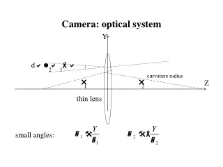
Active auto-focus system • Most of high-level DSCs provide focusable function which can improve the quality of image. Basically, the theorem of object captured by camera and the formation of image are shown in Fig. 1. Fig. 1. The diagram of camera focus.
Active auto-focus system (con.) • In the process of photo shooting, the correct lens position could be manually adjusted based on user’s experience. • In the active auto-focus system, active component such as infrared rays or ultrasonic component is used to help the lens to reach a suitable position. • Once the value of p is obtained, the proper value of q for lens position can be automatically controlled by an established motor controller in order to fit Eq. (1).
Passive auto-focus system • Passive auto-focus (PAF) is a technique to find the best focused lens position without active component. • A good sharpness measurement algorithm should obtain the higher sharpness value for the proper lens position to a well-focused image than an improper one. Fig. 2. The passive focus sharpness curve.
Passive auto-focus system (con.) • In our study, DWT and morphology edge enhancement algorithm were used for the sharpness measurement. • Furthermore, Self-organizing map (SOM) neural network controller was designed to control the adjustable lens to reach an accurate position. Fig. 3. The flowchart of the proposed system.
(#) The algorithms for sharpness measurement The algorithms for sharpness measurement
Haar transform Fig. A. original image Fig. B. after twice DWT
Haar transform • 1st Horizontal division
Haar transform (con.) • 2nd Vertical division
Lifting 5/3 DWT (1/3) • The procedure of Lifting 5/3 DWT can be mainly divided into two steps: • Splitting step: In this step, a raw data R with length n can be divided into two parts, the odd points r2i+1and even points r2i. They are denoted as and , respectively. Their mathematical expressions are given by • Lifting step: The high-pass elements and low-pass elements can be calculated by
Lifting 5/3 DWT (2/3) • In DWT, Lifting 5/3 is the simplest one which is shown in Fig. 4. Fig. 4. Lift 5/3 DWT diagram.
Lifting 5/3 DWT (3/3) Fig. 5. Frequency bands of DWT. (a) The focused image and (b) the blurred image.
Morphology sharpness measurement • For a briefly explanation, only dilation is reported in this paper. • A two-dimensional structuring element U with size nsx nsis defined. The operations are described as follows: • Dilation: In image processing, dilation operation can extend the boundary of an object by removing the low valued regions. After the dilation operation, new pixel can be obtained by the following equation: • Edge enhancement: The edge detector of image segmentation usually has a huge computational complexity. However, the morphology edge enhancement listed in Eq. (7) is simple and efficient. The operation of each pixel includes one subtraction and one dilation.
Morphology sharpness measurement (con.) • All obtained pixels (i.e., the preformed image ) can be summed up for the sharpness measurement and expressed as Fig. 6. The edge enhancement results of the well-focused and blurred images.
The proposed hybrid sharpness measurement • The ideal curve of sharpness versus lens position could be generally described as Gaussian curve. Fig. 7. The comparison of sharpness curves versus lens positions.
SOM neural network (#) SOM neural network
SOM neural network (1/8) • In the active auto-focus system, the best focused lens position is determined by the distance between object and camera. In PAF system, the best focused lens position searching needs to consider the optimal focused sharpness value. • But, the optimal focused sharpness value of a scene is usually unknown before the best focused position is reached. • In this study, a SOM neural network based controller is designed to find the best focused lens position.
SOM neural network (2/8) • The input layer and Kohonen layer are defined as vectors s and k respectively, and given by • Each neuron k in Kohonen layer k has the same dimension as input space s. Thus, a weight vector wi of k can be expressed as Fig. 9. SOM neural network model.
SOM neural network (3/8) • k is the training data which is the representative sharpness values of the fixed lens positions s0, s1, and s2.
SOM neural network (4/8) Fig. 8. Sharpness values of different objects with different lens positions.
SOM neural network (5/8) • The best-matching neuron of the input vector can be found by minimizing the Euclidean distance between s and wi two vectors. • Suppose the best-matching neuron index (i.e., the winner’s index) of the input layer s is denoted as b(s), then it can be determined by the following condition: • Once the best-matching neuron was found, the weight vectors then can be updated. The formula of weight vector adjustment is expressed as
SOM neural network (6/8) Fig B. Topological Structure Fig A. Two dimension Kohonen model
SOM neural network (7/8) • The pre-defined focused position (i.e. the revolutions of servo motor) can be given by z as shown in Eq. (17) which has the same dimensions as k. • In the hardware design, it can be stored in the read-only memory. • Once the input data is measured, the trained SOM neural network can determine the output category.
SOM neural network (8/8) • In the system we proposed, the neural network is firstly trained by an offline process. The well-trained SOM neural network is used to predict the best focused lens position. Fig. 10. The proposed searching method.
(#) Experimental results Experimental results
Experimental results (1/5) • Embedded system and hardware implementation • Adjustable lens module • a CMOS type image sensor with 100 K color pixels (i.e., 352 X 288) was used to capture images. • FPGA hardware design • Lift 5/3 DWT, morphology edge enhancement, and pulse width modulation (PWM ) controller are all implemented by a FPGA chip (Altera Cyclone EP1C12Q240C8). • Microprocessor • The system clock of high-speed 8051 microprocessor used is 100 MHz and the size of external SRAM is 64 KB. • PDA displayer • Microsoft .NET Framework. • The software is operated under the Windows Mobile 2003 operation system.
Experimental results (2/5) Fig. 11. The proposed PAF platform. Fig. 12. Adjustable lens module.
Experimental results (3/5) • To evaluate the performance of proposed system, this section presents the results of the sharpness measurement approach and search algorithm. Besides, the simulation results of each hardware function block implemented by Altera Quartus II 5.0 are shown in Table 1.
Experimental results (4/5) • Finally, we concluded that the best parameters of SOM can be obtained at the learning rate 0.977 and at the iteration number 100. • Basically, microprocessor will take much time in the image capturing and the sharpness measuring for a conventional PAF.
Experimental results (5/5) Fig. 15. The images of focus procedure.
Conclusions (#) Conclusions
Conclusions • In this paper, a passive auto-focus control system was designed and the new sharpness measurement scheme with SOM neural network based searching strategy was also proposed. • Advantages • Easy implementation by hardware • No active component • Rapid autofocus • Low image processing complexity • Drawbacks • However, in real case, the accurate estimation of the sharpness for an image with lower or excessive illumination is not easy.
Our Method (#) Conclusions ※因data不足,故捨棄SOM neural network
Search Method(1/6) • 三次曲線與二次曲線近似演算法 二次曲線與三次曲線近似演算法的實作方法可分為以下幾個步驟 Step 1: 移動取像直到△y發生正負變化 依據對焦量測準則結果的清晰度曲線分佈特性,我們將顯微鏡馬達每次的移動量(Moving Step)暫訂為顯微鏡馬達總行程的五分之一,開始移動取像並計算其對焦量測準則數值,紀錄上述的取像位置x與對焦量測準則數值y直到△y發生正負變化。 Step 2: 三次多項式近似 下式為三次多項式的數學表示式。若△y發生正負變化,則將之前所紀錄資料中對焦量測數值較大的前四筆變化資料取出來用Newton polynomial form建立可以表示此四筆資料分佈特性的三次多項式
Search Method(2/6) Step 3: 三次多項式求解 在數學上,三次多項式可以透過一次微分等於零f’(x)=0的方式來求的兩相異實根,一次微分等於零是在找切線斜率等於零的點。而三次曲線一次微分等於零的二點之中,其中一點就是我們在找的對焦點。 Step 4: 二次多項式近似 下式為二次多項式的數學表示式。將顯微鏡馬達移動到上次多項式近似時所求得的對焦點,取像並計算其對焦量測準則數值,將其紀錄資料中對焦量測數值較大及其左右二筆共三筆變化資料取出來用Newton polynomial form建立可以表示此三筆資料分佈特性的二次多項式。
Search Method(3/6) Step 5: 二次多項式求解 使用矩陣解法可以求得二次多項式的係數a、b及c,依據圖形曲線分佈得知其為一拋物線,我們可以用矩陣方式求解並以頂點公式 求得對焦點的位置。 Step 6: 判斷是否已經找到正確的對焦位置 將顯微鏡馬達移動到二次多項式近似時所求得的對焦點,取像並計算其對焦量測準則數值,將其取像位置及其對焦量測數值紀錄下來,並判斷其對焦位置是否與之前計算出的位置一樣,若一樣則表示已找到正確的對焦位置,若否,則繼續重複步驟4和步驟5。
20x A. Our Method B. Ground truth
20x001 A. Our Method B. Ground truth
40x A. Our Method B. Ground truth
40x001 A. Our Method B. Ground truth
Thank you. (#) Thank you