Download
1 / 8
80 likes | 154 Views
Communication Project 2005. Jyh-Ching Juang Department of Electrical Engineering National Cheng Kung University. Background. Several pico-satellite have employed CMOS camera as the payload. One example being the XI from University of Tokyo. Source: http://www.space.t.u-tokyo.ac.jp/cubesat/.

E N D
Communication Project 2005 Jyh-Ching Juang Department of Electrical Engineering National Cheng Kung University
Background • Several pico-satellite have employed CMOS camera as the payload. • One example being the XI from University of Tokyo Source: http://www.space.t.u-tokyo.ac.jp/cubesat/
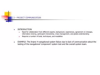
Objective • The objective of the communication project 2005 is conduct an experiment by integrating a CMOS camera module with a communication module. • Items that you are expected to learn • Principle of CMOS camera • Processing of image data • Data transmission through TNC modem • Packaging of image data and related protocol issues • Overall system integration • Computer programming • Hands-on experiences
System Schematic • The system is composed of several modules • CMOS camera • TNC modem • Computer • Peripherals • Others • Your group has to finalize the design
Requirements • The requirement is to acquire an image and transmit the image to your base station through a radio communication system with an acceptable image quality, transmission rate, and error rate.
Specifications • Image size: 320 x 240, color • Data transmission rate: 1200 bps • Frequency: 430 band • Transmission distance: at least 20 m • Test scenario • After you set up the camera and communication systems, two distinct time tags (say 10:00 am and 10:20 am) will be given. • The system is required to acquire the image at time tag 1, compress the image as required, and store the image in the memory. At time tag 2, the image data is sent to the receiver and the receiver is then required to display the image.
How to Start from Here? • Recommendations • Study related material • Data sheet • Existing design documents • Related products • Analyze and design the overall system configuration • Hardware • Software • Interface • Development tool • Build the system incrementally • Be a system engineer and work as a team
Final Report • Your final report shall contain three parts • Analysis report • assess the computational and communication loads of the system. More precisely, analyze the following related parameters: resolution, picture size, compression ratio, memory requirement, data transmission rate, and transmission time. • Design documents • System configuration • Hardware design • Software design • Test results • Demonstration