Download
1 / 45
540 likes | 940 Views
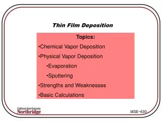
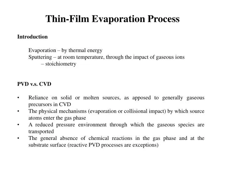
Thin-Film Evaporation Process. Introduction Evaporation – by thermal energy Sputtering – at room temperature, through the impact of gaseous ions – stoichiometry PVD v.s. CVD Reliance on solid or molten sources, as apposed to generally gaseous precursors in CVD

E N D
Thin-Film Evaporation Process • Introduction • Evaporation – by thermal energy • Sputtering – at room temperature, through the impact of gaseous ions • – stoichiometry • PVD v.s. CVD • Reliance on solid or molten sources, as apposed to generally gaseous precursors in CVD • The physical mechanisms (evaporation or collisional impact) by which source atoms enter the gas phase • A reduced pressure environment through which the gaseous species are transported • The general absence of chemical reactions in the gas phase and at the substrate surface (reactive PVD processes are exceptions)
Hertz Observation 1. Not limited by insufficient heat supplied to the surface of the molten evaporant. 2. Proportional to the difference between the equilibrium pressure, Pe, of Hg at the given temperature and the hydrostatic pressure, Ph, acting on the evaporant. He concluded that a liquid has a specific ability to evaporate at a given temperature.
Evaporation Rate • in number of atoms (or molecules) per unit area, per unit time • Φe = NAαe (Pe –Ph) (2πMRT)-1/2 • Φe = 3.513x10²² Pe (MT)-1/2 molecules/cm2-s • (M/NA) • Γe = 5.84x10⁻² Pe(M/T)1/2g/cm2-s (mass evap. rate) • αe is the evaporation coef., generally taken to be unity • Pe is the vapor pressure of the evaporant (in torr) • Ph is the hydrostatic pressure surrounding the evaporant • NA is Avogadro’s number • M is the molecular weight (g/mole) • Γe /D = cm/s D: film density Typical Γe = 10-4 g/cm2-s at 10-2 torr.
Vapor Pressure of the Elements Clausius-Clapyeron equation
10-3 torr at Melting Point Most metals evaporate using liquid phase. Cr, Ti, Mo, Fe, and Si evaporate using solid phase.
Evaporation of Multielement Materials Ionic compound Compound semiconductor alloys
Evaporation of Multielement Materials • Evaporation of compounds and alloys often yields films with different composition (See Table 3-1, Ohring) • Compounds: • Many compounds evaporate dissociatively and non-congruently (e.g. dioxides of Si, Ge, Ti, Zr) • III-V compounds, such as GaAs, are also good examples • Materials that evaporate non-dissociatively, e. g. CaF2, AlN, SiO, can be evaporated to form stoichiometric films • Some II-VI compounds, such as CdTe, evaporate dissociatively but congruently (with equal rates), such that compounds can be formed.
GaAs Phase Diagram at Low Pressures • Growth window must be As-riched • What will happen if Ga rich? • At 10-6 torr, the growth temperature must be between 630 and 1000 K. • What will happen if temperature fall out of this region? • Operation at a lower pressure narrows the usable deposition range.
Two-phase c(InSb) + v field is contracted compared with that of GaAs • Vapor pressure of Sb is less than that for As • Solidus line at lower pressure • Vapor pressure of In exceeds that for Ga • Vaporous line at higher pressure
Alloys: • evaporated flux equals source composition only if solution is ideal (i.e. Raoultian) -- seldom true • Roaultian law: vapor pressure of component B in solution is reduced relative to the vapor pressure of pure B (PB(0)) in proportional to its mole fraction XB. PB = XB PB(0) • deviations from ideality are common • PB = aB PB(0) where aB = gB XB • while evaporation rates can, in principle, be calculated if activities are known, the source composition changes continually • Solutions to the above problems, involving multiple evaporation sources
Al-Cu Alloy Deposition 2wt% Cu from single crucible heated to 1350 K
Maintaining Melt Stoichiometry • Evaporate from independent sources • Continuous addition of external mass
The number of B atoms added per second The number of B atoms lost by evaporation The number of B atoms accumulate in the melt Maintaining Melt Stoichiometry
Film Thickness Uniformity and PurityC Deposition geometry Thickness control
dAc Evaporation Source Point source Surface source
dAc Point Source n = 0
Knudsen Cell or Effusion Cell n=1 Cosine distribution flow through a hole
Supplements http://www2.ece.jhu.edu/faculty/andreou/495/2000/LectureNotes/PhysicalVaporDeposition.pdf
http://www2.ece.jhu.edu/faculty/andreou/495/2000/LectureNotes/PhysicalVaporDeposition.pdfhttp://www2.ece.jhu.edu/faculty/andreou/495/2000/LectureNotes/PhysicalVaporDeposition.pdf
http://www2.ece.jhu.edu/faculty/andreou/495/2000/LectureNotes/PhysicalVaporDeposition.pdfhttp://www2.ece.jhu.edu/faculty/andreou/495/2000/LectureNotes/PhysicalVaporDeposition.pdf
http://www2.ece.jhu.edu/faculty/andreou/495/2000/LectureNotes/PhysicalVaporDeposition.pdfhttp://www2.ece.jhu.edu/faculty/andreou/495/2000/LectureNotes/PhysicalVaporDeposition.pdf
Real Cell n Generally, the mass of material emitted from an evaporation source at a fixed angle is: m () = m cosn (n is related to source geometry)
Film Thickness d Thickness Point source Surface source
Example 1 It is desired to coat a 150-cm-wide strip utilizing two evaporation sources oriented as shown. If a thickness tolerance of 10% is required, what should the distance between sources be and how far should they be located from the substrate? It is obvious that the uniformity tolerance can always be realized by extending the source-substrate distance, but this is wasteful of evaporant.
Example 2 How high above any given source should a 25 cm diameter substrate be rotated to maintain the desired film tolerance of 1% in thickness? R = 20 cm, tolerance = 1% hv/R = 1.33, r/R = 0.6, hv = 1.3320 = 26.6 cm
Example 3 A clever way to achieve thickness uniformity For Knudsen source only
More about Thickness Uniformity • Physically, deposition thickness uniformity is achieved because short source-substrate distances are offset by unfavorably large vapor emission and deposition angles. • Uniformity of columnar grain microstructure, e.g., tilt, is not preserved, however, because of variable flux incidence angle. • Two principal methods for optimizing film uniformity over large areas involve varying the geometric location of the source and interposing static as well as rotating shutters between evaporation sources and substrates. • In addition to the parallel source-substrate configuration, calculations of thickness distributions have also been made for spherical as well as conical, parabolic, and hyperbolic substrate surfaces. • Similarly, cylindrical, wire, and ring evaporation source geometries have been treated.
Conformal Coverage and Filling of Steps and Trenches When a film of the same thickness coats the horizontal as well as vertical surfaces of substrates, we speak of conformal coverage. Step-coverage problems have been shown to be related to the profile of the substrate step as well as to the evaporation source-substrate geometry. • A “breadloaf” film topography evolves that tends to choke off further deposition in the trench. • As a consequence, a void may be trapped within, leading to a defective “keyhole” structure. • Collimation of the arriving atomic flux and heated substrates favor deeper and more conformal trench penetration, the former by minimizing shadowing and the latter by promoting surface and bulk diffusion of atoms.
Computer Modeling of Step Coverage Line-of-sight motion of evaporant atoms and sticking coefficients of unity can be assumed in estimating the extent of coverage. • In generating the simulated film profiles surface migration of atoms was neglected, which is valid assumption at low substrate temperatures. • Heating the substrate increases surface diffusion of depositing atoms, thus promoting coverage by filling potential voids as they form.
Film Purity Evaporant vapor impingement rate Gas molecule impingement rate Impurity concentration Ci
Vacuum Requirements • The chamber pressure during evaporation must be sufficiently low to minimize: • Scattering of evaporated species in the region between the evaporate source and the substrate • Minimized for pressures < 10-4 Torr, where the mean free path in air is ~45 cm. • background gas impurity incorporation into the film • depends upon the incorporation probability of the impurity into the film and the growth rate. • typical background species present in vacuum systems. • increasing the growth rate decreases the impurity content of evaporated films. • UHV systems are preferred when high purity films are required.
Contamination • In order to produce very pure films, it is important to deposit at very high rates while maintaining very low background pressures. Typical deposition rates from electron beam sources can reach 1000Å/s at chamber pressures of ~10-8 torr. • In sputtering processes, deposition rates are typically about two orders of magnitude lower and chamber pressures four orders of magnitude higher than for evaporation. Therefore, the potential exists for producing films containing high gas concentrations. (Not as “clean” a process as evaporation.) • Very high oxygen incorporation occurs at residual gas pressures of 10-3 torr. Advantage of this fact is taken in reactive evaporation processes where intentionally introduced oxygen serves to promote reactions with the evaporant metal in the deposition of oxide films.