Download
1 / 30
330 likes | 798 Views
Lithium Ion Sources for the Investigations of Fast Ion Transport in Magnetized Plasmas. H. Boehmer, Y. Zhang, W. Heidbrink, R. McWilliams, Department of Physics and Astronomy, University of California, Irvine, California 92697 D. Leneman and S. Vincena,

E N D
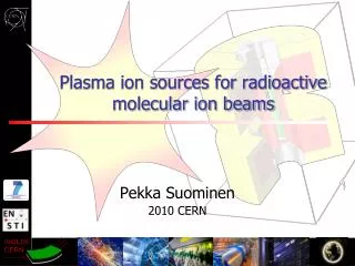
Lithium Ion Sources for the Investigations of Fast Ion Transport in Magnetized Plasmas H. Boehmer, Y. Zhang, W. Heidbrink, R. McWilliams, Department of Physics and Astronomy, University of California, Irvine, California 92697 D. Leneman and S. Vincena, Department of Physics and Astronomy, University of California, Los Angeles, California 90095
Abstract In order to study the interaction of ions of intermediate energies with plasma fluctuations, two plasma immersible Lithium ion sources of different size, based on solid-state thermionic emitters (Li-6 Aluminosilicate), were developed. Compared to discharge based ion sources, they are compact, have zero gas load, small energy dispersion, and can be operated at any angle with respect to an ambient magnetic field of magnitude generally found in plasma experiments. Beam energies range from 400 eV to 2.0 keV with typical beam current densities in the 1 mA/cm2 range. Because of the low ion mass of 6 amu, beam velocities of 100 – 300 km/s are in the range of Alfvén speeds in Helium plasmas. Design considerations and operation in a high vacuum test chamber as well as in the high density magnetized plasma of the LArge Plasma Device (LAPD) at UCLA will be detailed. The work is supported by DOE.
Fast Ions in Magnetized Plasmas • Definition: A plasma ion component whose energy is large compared to the thermal energy of plasma ions. • Generated by shocks and instabilities in space plasmas. • In fusion related plasmas they are formed by ionization of neutral beams, by ion cyclotron and lower hybrid heating and as byproducts of fusion reactions. • Anomalous transport frequently observed in toroidal plasmas. • Fast ion transport due to turbulence difficult to study in fusion devices: Lack of in situ diagnostics. • This program: Test particle transport in diagnostics accessible plasmas: High density, large volume LAPD plasma with small, internal ion sources.
Experimental Configuration of Fast Ion Transport Experiments in LAPD Plasma parameters: Diameter: 75 cm; Magnetic field 0.5 – 2 kG Pulsed at 1 Hz, peak density 2.5x1012 cm-3, Te = 10 eV Turbulence: Drift waves; Launched and unstable Alfvén Waves
Publications: H. Boehmer, et al., “Operation of a 0.2 – 1.1 keV ion source within a magnetized laboratory plasma”. Rev. Sci. Instr. 75, 1013 (2004) L. Zhao, et al., “Measurement of classical transport of fast ions”. Physics of Plasmas, 12, 052108 (2005) Y. Zhang, et al., “Lithium ion source for investigation of fast ion transport in magnetized plasmas”. Submitted to Rev. Sci. Instr.
Internal Fast Ion Beam SourcesFor LAPD • Required orbits: • Arbitrary pitch angle, helical orbits: Internal sources. Desirable Properties: • Wide energy range, 400 eV to 2 keV to investigate the energy dependence of the interaction. • Low ion beam mass to match the phase velocity of Alfvén waves in helium plasmas. • Low beam divergence to make the beam observable at large distances. • Sufficient current to facilitate diagnostics but small enough to prevent collective wave excitation (test particle investigation). • Small size and floating capability to minimize perturbation of background plasma. • Low gas load. • Operation at any pitch angle and at high magnetic fields. • No magnetic materials.
RF Ion Source for Fast Ion Experiments at LAPDRef.: H. Boehmer, et.al., Rev. Sci. Instr., 75, 1013 (2004) • Commercial source (IONTECH). • Operating frequency: 18 MHz. • Ion beam energy: 50 eV to 1200 eV. • Typical beam current density (Argon): 0.4 mA/cm2
Difficulty of Operating the RF Gun in a Magnetic Field • For ωce >> ωRF the gun plasma electrons are not sufficiently energized for gas ionization. • Operated at an angle with respect to an external magnetic field, only a fraction of the plasma is in contact with the extraction grids. • Beam energy: 600 eV.
Argon Ion Beam ProfilesMeasured in the Afterglow of the LAPD Plasma 32 cm from Ion Source
Disadvantages ofRF Source • Large gas load. • Operation at small magnetic fields and small pitch angles, only. • Large physical size. • Operation with Argon, only (large ion mass). Not adaptable to investigations for Alfvén wave interactions.
Surface Ionization Sources Ion species: Li, K, Cs, Ba. • Aluminosilicate source (Li)
Solid ceramic material loaded with the element to be emitted • Ion species: • Alkaline metals: Cs,K, Li6, Li7, Na. • Alkaline earth: Ba (“experimental”, LIF diagnostics). • Operation like electron guns with dispenser cathodes. • Typical beam densities: 1 mA/cm2 at 11500 C. • Inert at room temperature to atmospheric constituents. • Poisoned at operating temperature by O2, Vac. Oil, etc. • Lifetime depends on emission current. • Pulsed or DC operation.
Cross Section of a Generic Lithium IonSource for LAPD at UCLA • Two emitter sizes: 0.6 and 0.25” • Immersion in plasma and magnetic field: Pierce configuration not possible. • Gridded source. • Short emitter – grid distance: Orbit modifications by vxB and ExB forces small. • Development and tests at UCI. • For sufficient beam current at low beam energies (< 500 eV): acceleration-deceleration sections. • At high plasma densities (1012 cm-3): emitter current loaded by e-, geometric cut-off of plasma.
Lithium Ion Guns 0.60” dia.Emitter Size: 3.0” dia., 4.78” long 0.25” dia. Emitter Size: 1.285x1.260x1.630” Fits through 50mm port
Lithium ion gun with 0.6” EmitterEmission Current vs. TemperatureExtraction Voltage: 2 kV • Maximum achieved emitter current: 5.8 mA. • Typical current density: 1 mA/cm2 (at 2 mA)
Lithium Ion Beam Emission and Grid Transmissionfor 0.6” Diameter Emitter • Low emission current to prevent beam blow-up due to space • charge. • Space charge limited flow at low voltages. • Field enhanced emission at high voltages. • Grid transmission: 80%.
Equipotential Pattern in the Lithium – Ion Sources Improvement of Performance Dashed box: Space charge due to 1 mA/cm2, 600 eV beam included. • 0.6” Emitter: Fringing field errors and errors around grid wires are small at the useful center section. (b) 0.25” Emitter with single accelerator Grid: Fringing fields extend to center of the beam. Field errors around the 40 lpi 1st grid. (c) 0.25” Emitter with 90 lpi 1st grid. Addition of a second accelerator grid with 40 lpi.
Radial Beam Profiles in UCI Test Chamber Note: The beam current is intentionally kept low to avoid space charge blow-up of beam. • 0.6” Emitter w/o mask, 2.0 keV beam. Good beam profile with near parallel equipotential lines. (b) 0.25” Emitter. Blue: Single accelerator grid. Red: Double accelerator grid. Improvement of performance.
Beam Temperature is larger than the 1100o C Emitter Temperature0.25” Emitter Source, UCI Chamber 400 eV, ΔE = 3.7 eV 600 eV, ΔE = 12.3 eV 800 eV, ΔE = 15.0 eV ΔE/E = 2.0 % = const Note: The low energy tail of the distribution is probably due to a field error around the grid wires, an effect that becomes more severe with increasing beam voltage.
Ion Beam Detector and Analyzer for Operation inLAPD • Collector biased positive to reflect plasma ions. • Intermediate grid(s) biased negative to suppress plasma electrons. Caution: The Debye length is small compared to the grid holes during the active discharge: Double grids. • For sufficiently large pitch angles plasma components are shielded out geometrically.
Ion Gun Waveforms and Analyzer Signal in LAPD(1) During active discharge (2) During afterglow Interferometer signal Beam extraction voltage Emitter current Analyzer Signal
Lithium Ion Beam Profiles In LAPD 0.6” Emitter with 0.5 cm mask. (a) Profile 5 cm from gun. (b) and (c) Profiles at 32 cm from gun after one cyclotron orbit; Pitch angle = 280: Profiles appear elliptical. (b) At low plasma density in the afterglow. (c) At high density (> 1012 cm-3). The beam is attenuated and the centroid is shifted due to energy loss and/or plasma potential change: change in cyclotron radius.
Transverse Li-Ion Beam Profile in LAPDof 0.6” emitter with 0.5 cm aperture at 32 cm after 1 cyclotron period, pitch angle 28o
Emitter Lifetimes Shorter than Anticipated • Manufacturer quoted for typical emission current: 200 hrs. • Observed during operation in LAPD: 20 hrs. • Mechanism for decreased lifetime needs to be investigated. • Potential mechanism: Electron bombardment. (Private communication, E. Wolfrum, Max-Planck-Institut für Plasma Physik, Garching)_
Fast Ion Beam Interaction with Alfvén Waves in LAPD • Waves launched with current loops or disk antennas. • Wave field detected with 3 dim. dB/dt loops. Option I: • Single disk launches Alfvén cone. • Li ion beam with proper pitch angle transmitted through cone. Option II: • “Picture frame” antenna launches center wave. • Zero pitch angle beam transmitted on axis.
SAW AntennaeConfiguration and Field Pattern Fig. 2. Picture frame antenna (provided by T. Carter’s group) Fig. 1. 0.5 cm disk antenna (W Gekelman, S Vincena and D Leneman, Plasma Phys. Control. Fusion 39 (1997) A101–A112.)
Conclusion and Further Work • Two operational Lithium-6 ion sources with 0.6” and 0.25” diameter emitters developed. • First experiments performed at LAPD with quiescent and turbulent plasmas. • Further evaluation of emitter lifetime needed. • Development of in-house recoating of emitter material.