GCDB Data Adjustment Workshop: Enhancing GIS Accuracy
680 likes | 717 Views
Learn how to improve GIS spatial accuracy by connecting boundary data to the Geographic Coordinate Database (GCDB) in this comprehensive workshop. Discover the steps involved in adjusting GIS layers to the official representation of the Public Land Survey System (PLSS) - the GCDB. Access resources, tutorials, and scripts for adjusting data, and grasp the importance of aligning boundary data with the GCDB. Analyze data quality, review accuracy, and prepare for adjustments using control points and reference data.

GCDB Data Adjustment Workshop: Enhancing GIS Accuracy
E N D
Presentation Transcript
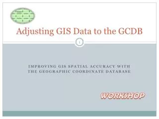
Adjusting GIS Data to the GCDB Improving GIS spatial accuracy with The Geographic Coordinate Database WORKSHOP
Montana’s Cadastral Data Are Based On & Connected To The GCDB
All Boundary Data Should Be Connected to the GCDB Because the GCDB was not universally available during early mapping efforts, many boundary GIS layers were connected to other GIS representations of the PLSS. In order to conform to today’s cadastral data, and the official representation of the PLSS (the GCDB), those data must now be connected to the GCDB. This workshop walks thru the steps to connect a GIS layer to the GCDB.
Objective The objective of this workshop is to inform on how to connect GIS boundary data to the GCDB.
Workshop Steps • Lesson 1: Gather & Organize the resources. • Lesson 2: Prepare the data for the adjustment. • Lesson 3: Perform the adjustment. • Lesson 4: Analyze the results. • Lesson 5: Follow up editing.
Graphic of the Basic Adjustment Process P1 P1 Old control point P1 New control point P1 Adjustment Vectors P2 P2 Old control point P2 New control point P2 Original Polygon Adjusted Polygon
Lesson 1 Gathering & Organizing the Resources
Montana’s GIS/GCDB Web Page • White Paper • PowerPoint Overview • PowerPoint Tutorial • Adjustment Script • Links to GCDB Information • Links to GCDB Data. http://giscoordination.mt.gov/cadastral/AdjustingDatatoGCDB.asp
Adjustment Data & Resources GIS Data to Adjust Reference & Source Data • Boundary GIS layer • GCDB Points (New Control) • Vertices from the Boundary GIS layer (Old Control) • Cadastral Adjustment Script
Pondera County Fire Districts Tutorial Data The example GIS data set is Pondera County’s Fire Districts. This dataset is not connected to the GCDB as shown in the accompanying illustration. The goal of this tutorial is to connect this GIS dataset to the GCDB. GCDB points GIS Layer vertices not coincident with GCDB
Gathering the GIS data sets GIS Data to Adjust • Create a project workspace; • Copy the boundary data to workspace folder; GCDB Reference Data ftp://ftp.gis.mt.gov/cadastralframework/GCDB Copy the GCDB file to the workspace folder OR …
Alternatively Connect to the Cadastral Map Service Connect to the GCDB map service via ArcCatalog: gis.mt.gov
Load the source data into ArcMap GIS Data to Adjust • Open ArcMap; • Add the boundary data to ArcMap;
Load and prepare the reference data GCDB Reference Data Add the GCDB points to ArcMap; Select the GCDB points that are within ½ mile of the boundary data; Save the selected GCDB points as a shapefile to the workspace folder. As shown on the following slides…
Select the GCDB points that are within ½ mile of the boundary data set.
Export the selected GCDB points to a shapefile Make sure that all your data sets have the same spatial reference
PLSS vs. Non-PLSS Boundaries River boundary PLSS boundary
Review your data quality • Review the spatial accuracy of the GCDB. • Review the quality of alignment of the Old Control to the New Control.
About GCDB Accuracy Each GCDB point represents the location of a township, or section, or ¼ section corner . Every GCDB point has an associated X coordinate accuracy estimate, and a Y coordinate accuracy estimate. The GCDB will serve as the reference frame for the boundary data. Therefore the boundary data will be no more accurate than the GCDB. Note: Other GCDB points may exist in some areas that represent locations in original PLSS surveys such as meander points along riparian areas, or mineral survey corners, and others.
How to review the spatial accuracy of the GCDB. • Right click on the GCDB layer and open its table; • Right click on the ERRORN or ERRORE fields and select STATISTICS from the pop-up menu. Your results should look similar to this: The error values are subjective estimates.
This is the range of errors of the coordinates in this GCDB data set.
Another way to look at the magnitude and distribution of errors is to map them.
Lesson 2 Preparing the data for the adjustment.
Control Point Files GCDB adjustments use 2 control point files. • The New Control is the GCDB (and sometimes additional points). • The Old Control comes from either an older GCDB (for data already connected to the GCDB), or from the vertices of the layer to adjust.
Two steps for creating the Old Control • Create the points (from the polygon vertices). • Assign GCDB IDs to those points. • Additional steps and processing may include: • Weeding out inappropriate or unnecessary points; • Creating non-PLSS control points.
Call the shapefile OldControl_NoIDS Points From Vertices Points from Polygon vertices: Generate points at the vertices of the polygon layer (Pondera Fire Districts). The points will be separate shapefile of points that will be the basis for the oringination vectors in the adjustment
To create a control file from the GIS features… • ArcINFO: • Toolbox: Data Management Features Feature Vertices to Points– creates a point layer from the polygon, or polyline vertices. • ArcEditor or ArcView • Use a third party utility such as ETGeoWizard or XtoolsPro to create a point layer from the polygon, or polyline vertices. The point layer will be used as the “OLD” control, so name it OldControl_NoIDs(we will add the IDs in a later step)
ArcInfo Feature Vertices to Points Save to a file in your workspace. Name the file OldControl_NoIDs
Assign the GCDB ID to each point in the OldControl_NoIDs OldControl vs New Control The Cadastral Adjustment will use the coordinates of the OldControl points and the NewControl points to generate the adjustment vectors. The basis for these vectors is the GCDB ID. GCDB point Vertex point
Join the NewControl to the OldControl_NoIDs Spatial Join OldControl_NoIDs Vertex points (green circles) The Spatial Join will assign to each point in the OldControl_NoIDs, the attributes of the GCDB (NewControl) points nearest to it. New Control GCDB points (red squares)
Save the new file as OldControl Spatial Join Right click on the OldControl_NoIDs in the TOC Joins & Relates Join Select : Join data from another layer based on spatial location Select the NewControl as the layer to join to OldControl_NoIDs Myworkspace\OldControl
GCDB IDs are now assigned to each point in the OldControl., along with the distance* to the nearest GCDB point (shown here in parentheses). However, there may be some duplication, as shown here (and on the next slide). Results of the spatial join * Note that the distance units returned by this operation are the units set in your data frame’s spatial reference (probably meters).
Dealing with duplicates Here 3 points in the OldControl have the same GCDB ID, however, only one is appropriate. Discuss some ways to deal with this. The distances to the nearest GCDB point are shown in parentheses.
Originally there were 3 vertices (green) One way to deal with the duplicate IDs in the OldControl, is to clean up the polygon layer first, in order to eliminate or reduce the number of vertices. This is a good solution in this example because the extra vertices should not be there. Here is the generalized polygon showing the reduced number of vertices. Instead of 3 vertices (green) in the original polygon, there is now only one Vertex (yellow) after generalizing the polygon. Resultant Single vertex (yellow) Nearest gcdb point Example solution – Generalize Polygon
Caution! Double Corners There can be double corners – especially along township lines. Make sure that you snap to the correct corner for each section!
Thin your OldControl File • Remove all points that are so far from the nearest GCDB point that they probably are NOT the same point. (use the distance field to identify them, e.g. distance > 60) • Remove all the meander points (“PointLab” like ’80%’) • Remove other points that are probably not PLSS points.
Thin your OldControl File • River Boundary Vertices vs. Meanders Remove meander points: Meanders vs vertices This GIS boundary follows the river in parts. Here we see the difference between the boundary vertices(green circles) versus the GCDB meander points (red squares). We do NOT want to use the meanders as control points, so we shall remove them (based on the IDs).
Meanders along waterways are not boundaries. Meander Points Meander corners are part of the original PLSS surveys along water ways. These points are represented in the GCDB with an 800 number series in the IDs. Meanders typically do NOT represent water boundaries, and should be removed from the control point files.
Other points to remove based on GCDB Code(PointLab) Remove these
How to Weed the OldControl Point File by selecting and deleting records. Weed by distance Remove meanders and other non essential points
Notes • If you have points in the OldControl that do not have a GCDB ID, those points will not get an assigned adjustment vector. So, the polygons at that location will move an amount that is proportional to its distance to the nearest adjustment vectors. • If you have some boundaries that you want to hold fixed in place (e.g. river ways or road ways), then give them dummy IDs and COPY them to the NewControl file. This gives those points (and the polygon edges that follow them) ZERO adjustment vectors.
Some boundaries should remain where they are. FIX in Place Select the OldControl points on boundaries that are NOT PLSS, and give them unique, non-GCDB IDS. Then, copy them into the NewControl file.