Download
1 / 20
220 likes | 548 Views
Atomic Absorption Spectroscopy. Lecture 14. Performance Characteristics of Electrothermal Atomizers.

E N D
Atomic Absorption Spectroscopy Lecture 14
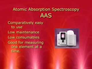
Performance Characteristics of Electrothermal Atomizers Electrothermal atomization is the technique of choice in case of small sample size. Also, higher sensitivities than flames are ordinarily obtained. Unfortunately, the analysis time is in the few minutes range and the relative precision is in the range of 5-10% as compared to 1% in flame methods. In addition, the linear dynamic range is usually small (~ two orders of magnitude) which requires extra sample manipulation. It may be also mentioned that better experienced personnel can achieve the merits of the technique.
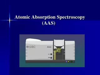
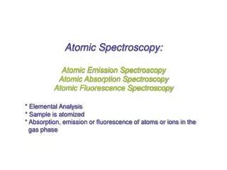
Atomic Absorption Instrumentation Atomic absorption instruments consist of a source of radiation, a monochromator, a flame or electrothermal atomizer in which sample is introduced, and a transducer.
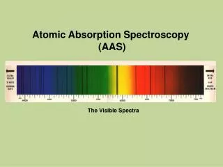
Radiation Sources Although radiation in the UV-Vis region is required, we can not use broad band sources. This is because even the best monochromators can not provide a bandwidth that is narrower than the atomic absorption line. If the bandwidth of the incident radiation is wider than the line width, measurement will fail as absorption will be only a tiny fraction of a large signal which is difficult to measure and will result in very low sensitivities (figure a). Therefore, line sources with bandwidths narrower than that of the absorption lines must be used.
This can be achieved by using a lamp producing the emission line of the element of interest where analyte atoms can absorb that line. Conditions are established to get a narrower emission line than the absorption line. This can in fact be achieved by getting an emission line of interest at the following conditions:
1. Low temperatures: to decrease Doppler broadening (which is easily achievable since the temperature of the source is always much less than the temperature in flames). 2. Lower pressures: this will decrease pressure broadening and will thus produce a very narrow emission line.
This may suggest the need for a separate lamp for each element which is troublesome and inconvenient. However, recent developments lead to introduction of multielement lamps. In this case, the lines from all elements should not interfere and must be easily resolved by the monochromator so that, at a specific time, a single line of one element is leaving the exit slit
Hollow Cathode Lamp (HCL) This is the most common source in atomic absorption spectroscopy. It is formed from a tungsten anode and a cylindrical cathode the interior surface of which is coated by the metal of interest. The two electrodes are usually sealed in a glass tube with a quartz window and filled with argon at low pressure (1-5 torr). Ionization of the argon is forced by application of about 300 V DC where positively charged Ar+ heads rapidly towards the negatively charged cathode causing sputtering. A portion of sputtered atoms is excited and thus emit photons as atoms relax to ground state. The cylindrical shape of the cathode serves to concentrate the beam in a limited region and enhances redeposition of sputtered atoms at the hollow surface.
High potentials usually result in high currents which, in turn, produce more intense radiation. However, Doppler broadening increases as a result. In addition, the higher currents will produce high proportion of unexcited atoms that will absorb some of the emission beam which is referred to as self absorption (a lower intensity at the center of the line is observed in this case).
Electrodeless Discharge Lamps (EDL) An EDL is a sealed quartz tube containing a few torr of an inert gas and a small quantity of the metal of interest. Excitation of the metal is achieved by a radiofrequency or a microwave powered coil through ionization of argon, due to high energetic radiofrequency. Ionized argon will hit the metal causing excitation of the atoms of the metal of interest. The output power of the EDL lamp is higher than the HCL lamp. However, compared to HCL lamps, EDL lamps are rarely used.
Emission in Flames There can be significant amounts of emission produced in flames due to presence of flame constituents (molecular combustible products) and sometimes impurities in the burner head. This emitted radiation must be removed for successful sensitive determinations by AAS, otherwise a negative error will always be observed. We can visualize this effect by considering the schematic below:
The detector will see the overall signal which is the power of the transmitted beam (P) in addition to the power of the emitted radiation from flame (Pe). Therefore if we are measuring absorbance, this will result in a negative error as the detector will measure what it appears as a high transmittance signal (actually it is P + Pe). In case of emission measurements, there will always be a positive error since emission from flame is an additive value to the actual sample emission. It is therefore obvious that we should get rid of this interference from emission in flames.
Absorbance is defined as: A = log (Po/P) However, in absence of a sample the detector will measure S1 , where: S1 = Po + Pe In presence of a sample, the detector will measure S2, where: S2 = P + Pe Therefore A = log (Po + Pe)/(P + Pe) At high absorbances, Pe may become much larger than P and the absorbance will be a constant since both Po and Pe are constants: A = log (Po + Pe)/(Pe)