Download
1 / 26
260 likes | 390 Views
DSM DTMROC version for the ATLAS TRT System Overview. DSM DTMROC version for the ATLAS TRT Chip Architecture. DSM DTMROC version for the ATLAS TRT Main Features. 16 low level differential ternary (Transition/Tracking/”0”) current inputs

E N D
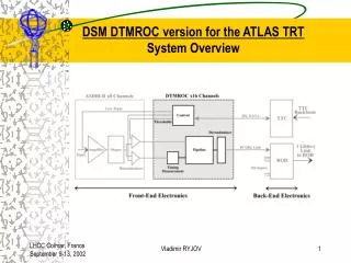
DSM DTMROC version for the ATLAS TRTSystem Overview Vladimir RYJOV
DSM DTMROC version for the ATLAS TRTChip Architecture Vladimir RYJOV
DSM DTMROC version for the ATLAS TRTMain Features • 16 low level differential ternary (Transition/Tracking/”0”) current inputs • On-board DLL generates 8 equally (3.125ns) spaced clocks • Tracking / Transition pulses sampling at 3.125 / 25 ns • 256 Pipeline locations = 6.25us latency (programmable) • 128 Derandomizer locations = 42 events • Two 6-bit and six 8-bit linear DAC’s • Programmable Test Pulses and Threshold voltages for the analog front-end chips • Fast self-trigger - “Wire Or” of selected input channels • Internal voltage sensing • SEU detecting and resistant circuitry • JTAG Scan Chain, Boundary Scan and RAM BIST test • Detailed Status monitoring Vladimir RYJOV
DSM DTMROC version for the ATLAS TRT Ternary Input translator • Tri-level differential current pulses > 4ns wide • 200µA current steps • Transition Radiation - 0 µA • Tracking pulse - 200 µA • No signal - 400 µA Vladimir RYJOV
DSM DTMROC version for the ATLAS TRT DLL and Time-digitizer • DLL employs 32 elements delay chain, phase detector and a charge pump • 8 equally spaced clock outputs used to sample straw track pulses • 50% duty cycle clock output can be selected to run the chip core logic Vladimir RYJOV
DSM DTMROC version for the ATLAS TRT Pipeline and Derandomizer Implementation • Pipeline memory space is built of 34 parallel synchronous dual-port SRAM banks of 1289-bit words. Total storage capacity is 256153-bit words. To avoid power consumption fluctuation, every odd SRAM bank has been connected to a True address bus and every even bank is driven by a Invertedaddress bus. • Derandomizer is acting as a FIFO. It is build of 17 parallel banks of the same SRAM. Total storage capacity is 128153-bit words (128/3 > 42 events). • Clock gating technique provides a power-efficient implementation (Clock/Trigger rate = 40MHz/75KHz) Vladimir RYJOV
DSM DTMROC version for the ATLAS TRTRead-Out • Full/Reduced read-out : 444/380 bits per event, including Header • LVDS-compatible, tristate drivers -> 40 Mbits/s copper links • “Wire-OR” – self triggering fast-out option. Selected ternary inputs contribute to the chip-level trigger. When multiple DTMROC are connected in parallel the currents add. Vladimir RYJOV
DSM DTMROC version for the ATLAS TRTDAC’s Each of the DAC consists of 256 identical PMOS slave current mirrors. Reference for the slave mirrors is provided by a current mirror master consisting of 128 PMOS unit devices (L=8um, W=5um)). The current mirror master is sandwiched between two DACs. Vladimir RYJOV
DSM DTMROC version for the ATLAS TRT Testability (1) • A general-purpose Status Register was introduced to indicate the status of the most important components of the DTMROC • Error bit representing the logical OR of all DTMROC error indicators is provided in the header field of output data stream (substitution of the DLL status bit) • All internal registers are equipped with the parity check logic • In addition to the DLL lock bit, a “watch dog” and a “dynamic” check circuitries examine the DLL outputs quality • JTAG Boundary-Scan is implemented as a serial shift register that is wrapped around the boundary of the chip • Special scan mode allows performing the extended production tests of the internal logic by configuring all DTMROC flip-flops as a large shift register controlled via JTAG interface • Pipeline and Derandomizer memories are equipped with Build-In-Self-Test (BIST) controlled via the Configuration register and JTAG interface Vladimir RYJOV
DSM DTMROC version for the ATLAS TRT Testability (2) - DLL control • “Static” DLL lock bit • “Watch dog” continuously compares rates of the external and internal DLL clocks • “Dynamic” tester examines the positions of 8 DLL outputs relative to the external clock Vladimir RYJOV
DSM DTMROC version for the ATLAS TRT Testability (3) - JTAG Logic Implementation • Supported instructions: • BYPASS - 11111 • EXTEST - 00000 • SAMPLE - 00010 • TEST - 00100 • IDCODE - 00001 • RUNBIST - 10000 • SCAN_PATH_TEST - 01000 • ID CODE capture value: • Manufacturer ID - 24 • Part Number - 4535 • Version Number - 3 Vladimir RYJOV
DSM DTMROC version for the ATLAS TRT Single Event Upsets Robustness and Detection • All internal registers are equipped with parity error check • The most critical parts are built of the SEU resistant and self-recovering elements based on triple logic with majority vote • Statistics circuit monitors the number of detected SEU’s Vladimir RYJOV
DSM DTMROC version for the ATLAS TRT Power UP and External Reset circuit Vladimir RYJOV
DSM DTMROC version for the ATLAS TRTDesign Tools issues A number of synthesis-layout cycles were done to generate design specific custom wire load models based on extracted parasitics and, therefore, to predict post-route timing with appropriate margins during RTL synthesis Vladimir RYJOV
DSM DTMROC version for the ATLAS TRT Synopsys and Layout path delay estimations Vladimir RYJOV
DSM DTMROC version for the ATLAS TRTChip Layout Die size 5.25.0mm² Vladimir RYJOV
DSM DTMROC version for the ATLAS TRTStatus • Submitted/fabricated in January/March 2002 • 850 chips tested on the mixed signal IMS Tester at CERN • 5 process corner (85/92/100/115/125%) evaluated • 79%Yield for 850 chips • Irradiation tolerance test at CEA Saclay Pagure facility in July 2002 • SEU sensitivity evaluated at the CERN PS in July 2002 • Test Beam at the CERN H8 in August-September 2002 Vladimir RYJOV
DSM DTMROC version for the ATLAS TRTWafer map with five Process Corners • Wafer size 8”, 350 µm • Die size 5.25.0 mm² • 1017 useable dies • 100 TQFP 1414 mm² Vladimir RYJOV
DSM DTMROC version for the ATLAS TRTPower consumption • Analog and Digital • Design estimate 130mA @ 2.5V 40MHz Process Variation Vladimir RYJOV
DSM DTMROC version for the ATLAS TRTSRAM performance Vladimir RYJOV
DSM DTMROC version for the ATLAS TRTTime measurements VDD = 2.5V VDD = 2.0V Vladimir RYJOV
DSM DTMROC version for the ATLAS TRTTotal Ionizing Dose tolerance • Tested at CEA Saclay Pagure facility in July 2002 • 7 Mrad total dose / 1.33 MeV gamma radiation • ~10% increase in the DAC’s output voltage after irradiation, no DNL change • No variations in the power consumption and the chip performance Vladimir RYJOV
DSM DTMROC version for the ATLAS TRTSEU sensitivity • Evaluated at the CERN PS irradiation facility in July 2002 • Integrated fluence of 1.81014p/cm2 on 24GeV beam • SEU cross-section for a single D flip-flop in different internal registers varies from 0.810-14 to 1.210-14 cm2 • The impact of SEU’s in the vital components is suppressed by self-recovering logic • Chip upsets resulting in spurious data affecting the event fragments synchronization in the back-end electronics are not excluded Vladimir RYJOV
DSM DTMROC version for the ATLAS TRTTest Beam Analyses Measurements of track position-resolution and hit-efficiency using the ASDBLR/DTMROC-S chip set were made at the CERN H8 test beam in August 2002. Drift time accuracy for a typical straw (right). The track radial position R versus drift-time dependence ”V” curve is also plotted (left). Vladimir RYJOV
DSM DTMROC version for the ATLAS TRTConclusions • A new version of the DTMROC designed in a deep sub-micron process has been fabricated and demonstrated to function. • Extensive lab tests give a high overall yield. • The process corner impact on the chip performance was examined. • The effectiveness of the radiation tolerant layout and design architecture techniques are confirmed. • Exhaustive internal test features were beneficial in simplifying and ensuring comprehensive design verification, high fault coverage and throughput. • Final production is scheduled for Q1 of 2003 Vladimir RYJOV