Download
1 / 36
400 likes | 628 Views
The Veloce Emulator and its Use for Verification and System Integration of Complex Multi-node SOC Computing System. Laurent VUILLEMIN Platform Compile Software Manager Emulation Division. Agenda. What is Emulation Use models Veloce Architecture Overview Veloce Software

E N D
The Veloce Emulator and its Use for Verification and System Integration of Complex Multi-node SOC Computing System Laurent VUILLEMIN Platform Compile Software Manager Emulation Division
Agenda • What is Emulation • Use models • Veloce Architecture Overview • Veloce Software • Practical : Use Veloce to verify Veloce
Agenda • What is Emulation • Use models • Veloce Architecture Overview • Veloce Software • Practical : Use Veloce to verify Veloce
Verification Challenges Software Systems Debug
Typical Development Cycle Fab Hardware Development Hardware Development System Integration Software Development Chip-level Verification Block-level Verification System Verification Time to Market Design Cycle
Typical System Development Fab Hardware Development System Integration Software Development Chip-level Verification Block-level Verification System Verification Time to Market Design Cycle
Software Simulation module counter (ck, en, step, dout); input ck, en; input [3:0] step output [3:0] dout reg[3 : 0] dout; always @ (posedgeck) begin if ( en ==1 ) dout= dout+step; end endmodule module counter (ck, en, step, dout); input ck, en; input [3:0] step output [3:0] dout reg[3 : 0] dout; always @ (posedgeck) begin if ( en ==1 ) dout= dout+step; end endmodule RTL Model Test bench Model is represented in Data Structures Compute and propagate signal values
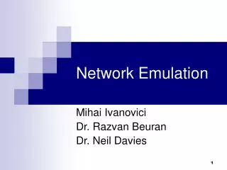
Clock Speed Scaling Stalls Emulation Required to Extend Performance Source: Recording Microprocessor History4/6/2012 Andrew Danowitz, Kyle Kelley, James Mao, John P. Stevenson, Mark Horowitz http://queue.acm.org/detail.cfm?id=2181798
Emulation module counter (ck, en, step, dout); input ck, en; input [3:0] step output [3:0] dout reg[3 : 0] dout; always @ (posedgeck) begin if ( en ==1 ) dout= dout+step; end endmodule Map RTL model in Programmable Logic Control execution and getresults Programmable Logic RTL Model • Multiples FPGA reproduce Model behavior from high level description
Agenda • What is Emulation • Use models • VeloceArchitecture Overview • Veloce Software • Practical : Use Veloce to verify Veloce
Modern SOC environment Embedded SW Debugger SoC PHY PHY PHY PHY USB Ethernet SATA CPU Display Processor SlaveIF Slave IF Slave IF Master IF Slave IF Arbiter Fabric Master IF Master IF Fabric CPU Software Memory PCIExpress RSP Slave IF Slave IF UART GPIO PHY JTAG
ICE use Model External Hardware Cables DUT The emulator is connected to actual Hardware Veloce
Ethernet Verification With ICE Ethernet Network Stimulus Generation / Analysis Tools Live Traffic iSolve Ethernet
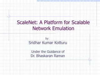
Co EmulationTestbench Xpress (TBX) • Testbench divided in 2 parts one in emulator the other in Station • Communication via transactor • Software sends commands that are interpreted by transactor to generate DUT stimulus Software Hardware Testbench PCI E 1/2 X-actor AGP 1/2 X-actor DUT Transactions USB 1/2 X-actor 1/2 X-actor High-speed Interface
Veloce Use Models Simulation Acceleration OVM/UVM SystemVerilog C/SystemC Accelerated Transactors SW Debug Codelink VProbe Fast ISS QEMU Software Debug Testbench Xpress Co-Model Channels Virtual Protocol Solutions Ethernet USB SATA Video PCIe VirtuaLAB Solutions Physical Protocol Solutions .... Physical I/O PCIe SATA Video USB Ethernet iSolve Solutions
Agenda • What is Emulation • Use models • VeloceArchitecture Overview • Veloce Software • Practical : Use Veloce to verify Veloce
Veloce2 Architecture Maximus2 AVB2 Crystal2 Chip X 16 X 64 + 40 SXB (Switch boards) + 4 CXB (clock board) Quattro2 16 AVB2 + 6 SXB (Switch boards) + 1 CXB (clock board)
Crystal 2 IC • Programmable Logic Array • Set of LUT an Sequential elements • Interconnect Network • Memories : • User Memories model • Virtual Wire Logic • Transport signals between chips • Debug Resources • Trace every Sequential element and memories • Triggers • Control • Load configuration • Control emulation Programmable Logic Array Control Debug Resources Virtual Wire Logic Memories
Agenda • What is Emulation • Use models • VeloceArchitecture Overview • VeloceSoftware • Compile Software • Runtime Software • Practical : Use Veloce to verify Veloce
Software Overview Network PC Farm Emulator host Compile Servers User design Configuration bitstream Runtime SW Low Level SW Compile SW Transform design in bistream User Interface Control Emulator Collect debug data
Compile software Design +Testbench TBX Partition Testbench between SW and Emulator RTL RTLC Perform RTL Synthesis Gate netlist Partitioning in Crystal Sytem Routing Crystal Place and Route Ressource Allocation Platform Compile Bitstream
Runtime Software Ressource Server Maintenance Server Emulator Message Bus Emulator Host Server Runtime Server LLSW User Message Bus Visibility Server UI Veloce DAC 2014
Agenda • What is Emulation • Use models • VeloceArchitecture Overview • Veloce Software • Practical : Use Veloce to verify Veloce • Challenges • The verification infrastructure • Verifying ASIC • Verifying the Compilation software • Low level software integration • Firmware validation debug • Runtime software integration
Challenges • Complex system • ASIC • FPGAs Firmware • Mutliple software components • Verifying all component of the system and their interactions • Time to get a bug • Size : • Detailed model of a full Emulator of next generatio will not fit in current generation
Addressing the challenges Use a comodel approach for more abstraction level and connection with the software Divide verification in steps based on functionality Simplify the model by using different abstraction level depending on what functionality is tested Veloce DAC 2014
Verification Infrastructure More details on Veloce LLSW on host Control Chip Crystal Crystal Control Control Veloce Control Bus Control Commands Veloce
Verification Infrastructure Emulation model Emulator Software Control Chip Transactor Crystal Crystal Control Control Veloce Control Bus Nature of the Software, Transactor and Model in emulator depend on abstraction level Veloce
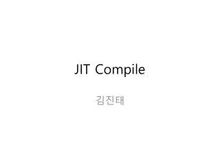
ASIC verification : example of Trace Emulation Model Data Comodel SW DDR Crystal DDR Controler Transactor Control SW translator Macro Block Trace control Trace Capture Design VeloceComands Trace Capture, Trace Control and DDR Controler are Accurate models Design is a gate level netlist generating random data Data are either manually generated or come from actual compile Run million cycles on multiple designs Veloce
Verification of compile SW Emulation Model Bitstream Comodel SW Crystal Transactor Configuration Block Control LLSW Bitstream reader Macro Block VeloceComands Macro and Configuration blocks are Accurate models Bitstream is the output of actual compile flow Verify behavior of design Veloce
Verification of Low Level Software 1/2 Example : Virtual Wire Synchronisation Data multiplexed on serial link Crystal Crystal Virtual Wire Logic Virtual Wire Logic Control Control Virtual Wire need a training/Calibration sequence This sequence is controled by Low Level Software Veloce
Verification of Low Level Software 2/2 Emulation Model Comodel SW Transactor Control Chip Actual LLSW Crystal Crystal Control Control VW Block VW Block Control block in Crystal and VW block are accurate model Actual LLSW communicate with the model through comodel SW and transactor Veloce
Verification of Firmware 1/2 Example : Trigger Reduction CXB FPGA System Level reduction Crystal Crystal Crystal Crystal Trigger Logic Trigger Logic Trigger Logic Trigger Logic FPGA FPGA AVB Level reduction AVB Level reduction AVB AVB Macro Block Macro Block Macro Block Macro Block A trigger express a condition on values coming from the design At AVB and System level it is implemented in FPGA A binary is genrerated by runtime SW to express condition Veloce
Verification of Firmware Emulation Model Trigger binary Comodel SW Transactor CXB Control FPGA System Level reduction Crystal Crystal Crystal Crystal Trigger Logic Trigger Logic Trigger Logic Trigger Logic FPGA FPGA AVB Level reduction AVB Level reduction SW translator AVB AVB Macro Block Macro Block Macro Block Macro Block VeloceComands Design is modeled as gate level netlist Trigger binary is generated by actual runtime SW Verify behavior of trigger in multiple design sequences Veloce
Runtime SW Verification Ressource Server Emulation Model Emulator Host Server Transactor LLSW Emulator Message Bus Crystal Control Comodel SW Runtime Server Macro Block Design User Message Bus Memories UI Actual Runtime Server is used High level model for the HW Veloce
Questions Veloce