Download
1 / 40
400 likes | 542 Views
Conceptual Modeling and Analysis of Drag-Augmented Supersonic Retropropulsion for Application in Mars Entry, Descent, and Landing Vehicles. Michael Skeen Ryan Starkey University of Colorado at Boulder Department of Aerospace Engineering Sciences 10 th International Planetary Probe Workshop

E N D
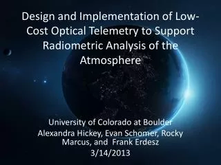
Conceptual Modeling and Analysis of Drag-Augmented Supersonic Retropropulsion for Application in Mars Entry, Descent, and Landing Vehicles Michael Skeen Ryan Starkey University of Colorado at Boulder Department of Aerospace Engineering Sciences 10th International Planetary Probe Workshop Cross-Cutting Technologies IV Session San Jose, CA June 21, 2013
Overview • Introduction and Background • Problem Statement • Drag-Augmented Supersonic Retropropulsion • Aerodynamic Modeling • Ballistic Coefficient Comparison • Drag Coefficient Modeling • Validation and Sensitivity Analysis • Trajectory Modeling • Drag-Augmented SRP Operation • Hybrid Decelerator Systems • Conclusions and Future Work M. Skeen IPPW 10
Mass Limitations Problem Statement M. Skeen IPPW 10
Supersonic Retropropulsion (SRP) Supersonic Decelerators Flowfield sketch: Korzun, 2012 Central Nozzle Configuration CFD images: Bakhtianand Aftosmis, 2011 M. Skeen IPPW 10
Supersonic Retropropulsion (SRP) Supersonic Decelerators Flowfield sketches: Korzun, 2012 CFD images: Bakhtianand Aftosmis, 2011 Peripheral Nozzle Configuration M. Skeen IPPW 10
Drag Trends High- Thrust SRP Drag- Augmented SRP Supersonic Decelerators (Bakhtian and Aftosmis, 2011) M. Skeen IPPW 10
Ballistic Coefficient Comparison • Ballistic coefficient including SRP • What CD is required to match IAD ballistic coefficient? • Solve for • Drag augmentation ratio Ballistic Coefficient M. Skeen IPPW 10
SRP vs. SIADs = 1.5 Ballistic Coefficient M. Skeen IPPW 10
Shock Cascades Patm Patm Shock angle: 40° 6.9x Patm Isentropic Isentropic P0 P0 Isentropic P0 4.0x Normal Shock Oblique - Normal Shock Cascade Supersonic Decelerators Oblique-Oblique-Normal Shock Cascade Bakhtian and Aftosmis, 2011 M. Skeen IPPW 10
Drag Model Methodology Aerodynamic Modeling Korzun, 2012 Shock structure (grey) caused by SRP plumes (orange). Coefficient of pressure shown on aeroshell surface. (Bakhtian and Aftosmis, 2011) M. Skeen IPPW 10
Pressure Model • Normal shock • Accelerated flow near capsule periphery • Oblique-normal shock cascade • Oblique-oblique normal shock cascade • Separated flow • Nozzle exit flow Aerodynamic Modeling CFD (Bakhtian and Aftosmis, 2011) Pressure Model M. Skeen IPPW 10
Drag Coefficient Model Results + 14% Aerodynamic Modeling M. Skeen IPPW 10
Model Validation Aerodynamic Modeling * Nozzles placed at a radius of 55% of the aeroshell diameter. ⌂ Nozzles places at a radius of 80% of the aeroshell diameter, cone half angle of 60°. † Thrust coefficient of 1.5. M. Skeen IPPW 10
Sensitivity Analysis – ON Flow Region Size Aerodynamic Modeling M. Skeen IPPW 10
Trajectory Model • 3 degrees of freedom • Planar movement only • Mars GRAM atmosphere • Time and location averaged • MSL initial / parachute deployment conditions • Ballistic trajectory reference (1135 kg) Trajectory Modeling • Solver Target • Parachute deployment (q∞, M∞ conditions) • Iterate mass so parachute deploys at 10 km altitude • Vehicle mass at parachute deploy → usable mass M. Skeen IPPW 10
Drag Coefficient Sensitivity 2.5 % Trajectory Modeling • Mass has low sensitivity to drag coefficient changes • Does not take into account operation methodology M. Skeen IPPW 10
Peak Dynamic Pressure Region Trajectory Modeling M. Skeen IPPW 10
Drag-Augmented SRP Results Trajectory Modeling • Maximum Mass: Constant SRP Operation • Entry: 4433 kg (+ 232%, +3098 kg) • ‘Dry’: 1786 kg (+34%, +451 kg) • Baseline Vehicle • Entry: 1335 kg • ‘Dry’: 1335 kg M. Skeen IPPW 10
Drag-Augmented SRP Results (2) Trajectory Modeling • Maximum Mass: Constant SRP Operation • Entry: 4433 kg (+ 232%, +3098 kg) • ‘Dry’: 1786 kg (+34%, +451 kg) • SRP Operation Below 50 km • 98.8 % of mass performance M. Skeen IPPW 10
Constant Thrust Trajectory Trajectory Modeling • Maximum Mass: Constant SRP Operation • Entry: 6690 kg (+ 401%, +5355 kg) • ‘Dry’: 1431 kg (+7%, +96 kg) • or Dynamic Pressure Targeted Operation • Entry: 3289 kg → 65% less propellant • ‘Dry’: 1449 kg (+9%, +114 kg) M. Skeen IPPW 10
SRP-IAD Hybrid Trajectory Modeling • Maximum Mass: Transition to IAD • Entry: 12947 kg (+ 870%, +11612 kg) • ‘Dry’: 10770 kg (+708%, +9435 kg) • ‘Dry’ Mass Fraction: 83% • Baseline Vehicle • Entry: 1335 kg • ‘Dry’: 1335 kg • ‘Dry’ Mass Fraction: 100% M. Skeen IPPW 10
Summary Aerodynamic Modeling • IAD systems provide lower ballistic coefficient • Drag coefficient model for drag-augmented SRP • Analytic model + computational results • Drag coefficient can increase by 14% • Validation and sensitivity analysis Trajectory Modeling • Ideal drag-augmented SRP increases ‘dry’ mass by 34% • Operation in maximum dynamic pressure regime critical to efficacy • 65% savings in propellant for constant-thrust case • Hybrid decelerator systems take advantage of appropriate flight regimes • SRP-IAD hybrid increases ‘dry’ mass by 708% Summary M. Skeen IPPW 10
Future Work SRP Modeling • Expand SRP aerodynamics database • Experiment or CFD • Analytic or semi-analytic modeling of SRP shock structure • Correlation with thrust coefficient • Angle-of-attack model development • Asymmetric thrust operation Systems Analysis • Sensitivity to additional performance parameters (CT, Isp, angle of attack, entry conditions, aeroshell size, etc.) • Maneuvering flight analysis, landing uncertainty • Conceptual vehicle design (aeroshell design, thermal environment, hardware system selection, component sizing, etc.) Summary M. Skeen IPPW 10
Acknowledgements • Dr. Ryan Starkey • Busemann Advanced Concepts Lab • CU Aerospace Engineering Department • Funding support through TA and CA programs • Student Organizing Committee • Student Scholarship Sponsors M. Skeen IPPW 10
Pressure Model Assumptions • Isentropic compression between shock structure and aeroshell • No ‘mixing’ of flow regions • Neglecting ablation, chemical reaction, boundary layer effects • Symmetric pressure distribution about each quadrant (symmetric in thirds for 3 nozzle configurations) • Flow region sizes remain constant with all parameters • Pressure distribution corresponds to CT=1.5 • Pressures vary radially in same manner as nominal capsule flow structure • Flow is accelerated around nozzle exit • Oblique shock angle of 40° • Constant backshell pressure • Neglect flow turning through shock cascades • Steady state model Aerodynamic Modeling M. Skeen IPPW 10
Grid Size Sensitivity Aerodynamic Modeling M. Skeen IPPW 10
Real Gas Effects Aerodynamic Modeling M. Skeen IPPW 10
Sensitivity Analysis – Specific Heat Effects Aerodynamic Modeling M. Skeen IPPW 10
Sensitivity Analysis – Shock Wave Angle Aerodynamic Modeling M. Skeen IPPW 10
Sensitivity Analysis – Back Face Pressure Aerodynamic Modeling M. Skeen IPPW 10
Sensitivity Analysis – NS Flow Region Size Aerodynamic Modeling M. Skeen IPPW 10
Sensitivity Analysis – Accelerated Flow Region Size Aerodynamic Modeling M. Skeen IPPW 10
Sensitivity Analysis – OON Flow Region Size Aerodynamic Modeling M. Skeen IPPW 10
Sensitivity Analysis – Separated Flow Region Size Aerodynamic Modeling M. Skeen IPPW 10
Sensitivity Analysis – Nozzle Exit Area Aerodynamic Modeling M. Skeen IPPW 10
Drag-Augmented SRP Results (3) Trajectory Modeling M. Skeen IPPW 10
SRP Propellant Mass Trajectory Modeling M. Skeen IPPW 10
SRP Hybrid Drag-Augmented → High-Thrust Trajectory Modeling • Maximum mass performance occurs for fully high-thrust SRP • Low ‘dry’ mass fraction M. Skeen IPPW 10
SRP Hybrid Drag-Augmented → High-Thrust Trajectory Modeling • Maximum mass performance occurs for fully high-thrust SRP • Low ‘dry’ mass fraction M. Skeen IPPW 10