Download
1 / 17
170 likes | 336 Views
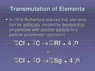
Characteristics of Transmutation Reactor Based on LAR Tokamak Neutron Source. B.G. Hong Chonbuk National University. CONTENTS. Concept of Fusion Driven System Neutron Source Based on LAR Tokamak Transmutation Characteristics Summary. Transmutation System. High level waste from NPP

E N D
Characteristics of Transmutation Reactor Based on LAR Tokamak Neutron Source B.G. Hong Chonbuk National University
CONTENTS • Concept of Fusion Driven System • Neutron Source Based on LAR Tokamak • Transmutation Characteristics • Summary
Transmutation System • High level waste from NPP • Long-lived TRU: Pu • Long-lived MA: Np, Am, Cm • Long-lived FP: Tc, I, Sr, Cs • Transmutation methods proposed • Fast reactor: SFR, LFR, GFR • ADS (Accelerator Driven System) • FDS (Fusion Driven System) • Fission to capture ratio is high for fast neutron spectrum
Fusion Driven System Fusion: neutron-rich reaction Fission: energy-rich reaction n, 14 MeV Blanket: 6Li+n→4He+3H + 4.8 MeV 7Li+n→4He+3H+n‘ - 2.5 MeV (AC, FP)+n→ X + energy Plasma: D+T→4He+n+17.6 MeV
Output Energy of FDS • Output electrical energy from a FDS From fission From fusion Efus 17.6 MeV/n effciency of collecting and converting to electricity the plasma heating energy and the energy produced by fusion. Qp Fusion energy multiplication εratio of energy produced by other exoergic reactions to the energy produced by fission. average number of neutrons per fission Efis195 MeV/fission efficiency of energy conversion in blanket • For 500 MWe, Sfus ~ 1019 -1020n/s-> Fusion power ~ a few hundred MW
Neutron Source • Neutron source based on a LAR tokamak concept allows a compact reactor and a elongated plasma shape which is favorable for a transmutation reactor • Look for compact neutron source (LAR tokamak) within physics and technology adopted in ITER design: Sfus ~ 1019 -1020 n/s → Pfus ~ a few hundred MW • Pfusion = 150 ~ 500 MW, aspect ratio A = 1.5 ~ 2.5 • Transmutation in blanket 1 by 14 MeV neutron and T-breeding in blanket 2 by neutron produced by fission of wastes. Enrichment of Li-6 may not be necessary
LAR Tokamak Neutron Source • Reactor components must satisfy plasma physics and technology constraints • Plasma performance characterized by normalized beta, βN, confinement improvement factor, H and ratio of density to Greenwald density limit, n/nG. • k = kmax, qa = qa,min, d = 0.3, βN = βN,max,H = 1.2, n/nG =1.0 withkmax, qa,min,, βN,max from LAR tokamak physics scaling. • Shielding requirement for a 40 FPY lifetime with 75 % availability • fast neutron fluence < 1019 cm-2 • radiation dose < 109 rad • displacement damage limit < 10-3 dpa • By both fusion and fission neutron • Blanket • For Tritium self-sufficiency, TBR (Tritium breeding Ratio) > 1.05 • Neutron multiplication keff< 1.0 for sub-criticality • Maximize transmutation rate
Geometry Composition of KSNP spent fuel
Analysis Method • Self-consistent coupled analysis • Fusion physics and technology: Systems analysis • Blanket: Radiation transport, Burn-up • BISON-C code • Li burn-up considerd
Optimum Radial Build of a Neutron Source • The minimum major radius R0 decreases as A increases • For large A and large fusion power, large neutron wall loading & large shield thickness. • The required auxiliary heating power increases as the aspect ratio increases. • When A= 2.5, the magnetic field @ TF coil increases as the fusion power increases and the minimum major radius R0 is determined by the maximum magnetic field(~ 13 T) A=2.0 A=1.5
TRU Transmutation • A=1.5, BL1= 20.2 cm • TRU 5%, He 75%, SUS316 15%, SiC 5% in Blanket 1 • PbLi 90% (Nat. Li), He 7%, SUS316 3% in T-breeding blanket • A=2.0, BL1= 21.7 cm • A=2.5, BL1= 22.5 cm • Transmutation rate is large for large A case due to large GN. • But the major radius and the reactor height (~ k·a), decreases as A increases, and loaded TRU amount is smaller than the small A case.
5-Batch Equilibrium Fuel Cycle Blanket 1 plasma plasma plasma 1st plasma 2nd plasma plasma plasma plasma 4th 3rd plasma plasma 5th FDS Disposal or reprocessing
Transmutation Characteristics • 5-batch fuel cycle, blanket height = ½ k∙a • For the burn-up fraction to be 50%, fusion power of 500 MW and the burn cycle of 5,000 day are required for A =1.5. → With one unit of the transmutation reactor, more than 3 PWRs (1.0 GWe capacity) can be supported considering that the TRU from 1 PWR (1.0 GWe capacity) is about 250 kg/y. • Less fusion power and less burn cycle are needed for A > 2.0 for the burn-up fraction to be bigger than 50 %, but less than 3 PWRs can be supported. • Natural Li can be used for the small A case with the small fusion power and the short burn-up cycle, while Li-6 needs to be enriched for the large A case with the large fusion power and the long burn-up cycle.
Minor Actinide Transmutation • Pfusion = 150 MW, A = 2.0 • MA2O3 50%, He 35%, SUS316 15% with BL1= 8.2 cm for keff < 0.95 • BL2: PbLi 90% (Nat. Li), He 7% and SUS316 3%, BL2 determined by condition TBRav > 1.35 • Keff, power and T.R. initially increase but decrease as the MA burns up.
Transmutation Characteristics • For MA transmutation, the largest MA transmutation rate is 479 kg/y with a 5,000 day burn cycle The burn-up fraction increases with residence time. • For the TBRav > 1.35, DBL2 increases with the burn cycle and 40 cm is necessary for 7,500 days, which is smaller than the case with the TRU. • 13 PWRs (1.0 GWe) can be supported with one unit of the transmutation reactor based on the LAR tokamak producing 150 MWth of fusion power.
Fusion Driven System: Pros and Cons • Physics and technology design basis for a tokamak DT fusion neutron source exists today (ITER) • Existing nuclear technology can be applied and GEN-IV will improve the concept. • A fusion source can produce a sharp spectrum of 14 MeV neutrons, compared with the distributed spectrum of an accelerator source. • 14 MeV neutrons can induce various neutron-multiplying reactions easily, can fission all actinides. • FDS might have more safety problems, as it basically combines a fusion reactor with a fission reactor in a tight system. • Using a fusion source will require tritium, and therefore will increase overall radioactivity. • Blanket geometry in fusion reactors is not ideal fission reactor geometry. Specifically, a tokamak fission blanket will have very high fuel inventory, compared with an accelerator driven fission reactor.
SUMMARY • Concept of a transmutation reactor based on LAR tokamak is investigated as a feasible option for reducing high level, long-lived waste. • For self-consistent calculation of the system parameters, the systems analysis was coupled with the radiation transport code, BISON-C. • Within the ITER physics and engineering constraints, up to 3 PWRs (1.0 GWe capacity) can be supported with one unit of the transmutation reactor based on the LAR tokamak producing 150 ~ 500 MW of fusion power with the aspect ratio A = 1.5 ~ 2.5 for transmutation of TRU. • For transmutation of MA, 13 PWRs (1.0 GWe) can be supported with one unit of the transmutation reactor based on the LAR tokamak producing 150 MW of fusion power.