Download
1 / 20
200 likes | 378 Views
The ESA MUSIC Project Design of DSP HW and Analog TX/RX ends. Advanced Mobile Satellite Systems & Technologies presentation days ESA/ESTEC – 14-15 November 2000. Presentation Outline. The PROTEO Signal Processing Board The MUSIC TX/RX Analog Signal Conditioning Units.

E N D
The ESA MUSICProjectDesign of DSP HW and Analog TX/RX ends Advanced Mobile Satellite Systems & Technologies presentation days ESA/ESTEC – 14-15 November 2000
Presentation Outline • The PROTEO Signal Processing Board • The MUSIC TX/RX Analog Signal Conditioning Units
PROTEO Board Main Features Summary • 12 bit pipelined ADC Converter (BB ADS807) up to 53MHz sampling. • 100 KgatesCPLD (Altera Flex EPF10K100A): - clock >100MHz; - usable gates: 90%; - embedded array blocks: 12 (ex. RAM, ROM, FIFO functions); - in-circuit re-configurability via Byte-Blaster or JTAG port. • 66 MIPS 16bit DSP (ST18952). • On board Memories: - x CPLD: SRAM 256Kx16 & SIMM-like Module for SRAM 1MB or SDRAM 4MB; - x DSP : SRAM 64Kx16, FLASH 4Mx16. • Master Clock distribution by Prog. Skew Clock Buffer (Cypress CY7B991): - selectable skew to 18ns (+-12 time units of 1.5ns). • Prog. Clock Generator (Cypress ICD2053B) for CPLD only: - clock out : 391KHz-90MHz; - prog. "on the fly" by 2 wire serial interface. • 2x 12 bit dual DAC converters (Analog Device AD5323) : - high-speed serial interface control logic (up to 30 MHz).
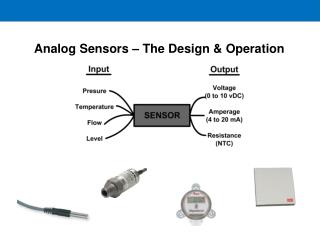
MUSIC TX - System requirements • IF Carrier Frequency: 70MHz • Max Carrier Frequency Uncertainty: +/-100 Hz • TX Output Power Level: -10 to -30 dBm • Spurious and Harmonics: <40 dBc • In-Band Ripple: <0.1 dB
Active Mixer: Analog Device AD831 LO Drive required (min): -10 dBm P1dB: +10 dBm IP3: +24 dBm Control via IEEE488 Mixer fIF fIFD AWG NOISE Download Signal GENERATOR via IEEE488 +MAI B-P Arbitrary fLO Low-pass Waveform Filter 1 Filter TCXO Generator T Signal TestPoint +MAI TCXO: Fordahl DFA 36-MS Nom Frequency: 65.536 MHz Output Load: Sine 0 dBm (50 Ohm) Frequency stability: +/- 1 ppm SAW Filter: SAWTEK 854657 1-dB Bandwidth: 3.25 MHz Insertion Loss: 7.7 dB In-band ripple: 0.8-1 dB Group delay in spec LC Butterworth Low-pass Filter Order: 5 3-dB Bandwidth: 7.5 MHz +Noise L.O. TX SECTION Ext.in LO 65.536 MHz Up-conversion TX boardBlock Diagram
P1dB Measurements • P1dB (input): +10 dBm
In-band ripple (Pin=0dBm): 1 dB Harmonics and in-band ripple • Max Outband spurious level: -44 dBc • Isolation LO to Output: -65 dB
Op-Amp: TL082 to IF 70MHz MUSIC Receiver IF N 1V p-p TP Signal Digital Section Diff.out +MAI BALUN fIF +Noise B-P Filter 2 VGA 1 VGA 2 RX SECTION Amp2 Amp1 TP SAW Filter: SAWTEK 854657 1-dB Bandwidth: 3.25 MHz Insertion Loss: 7.7 dB In-band ripple: 0.8-1 dB Group delay in spec VGA: Philips SA5219 Bandwidth: 700 MHz 7 dB Noise Figure Min 0-1V gain control pin RSSI: Analog Devices AD8307 Dynamic range: 92 dB Slope: 25 mV/dB 1 pole RC filter Op-Amp: TSH31 - Low-Pass filter BUFFER LOG AMP RSSI + Vref MUSIC RX AGC boardBlock Diagram error signal
VGA 2 VGA 1 Amp2 Amp1 - BUFFER LOG AMP RSSI + Vref Loop gain Loop Bandwidth Control loop IF 70MHz IF N 1V p-p to TP Signal Diff.out +MAI MUSIC Receiver BALUN fIF +Noise Digital Section B-P Filter 2 RX SECTION TP Loop error Low-Pass filter Loop stability!!
Loop Bandwidth • Loop Bandwidth must be limited in order to avoid input signal modulation. • Loop bandwidth fixed: 200 Hz • Loop gain: ~20 dB
HP-ADS Simulation Input Signal • Input Signal Average Power Dynamics: 20 dB • Average Fading rate: 20dB/3ms
HP-ADS Simulation Results • 20 dB Input Power Dynamics • 1 dB Output Power Dynamics
Conclusions • Implementation of TX and RX boards • Testing and measurements has confirmed simulations results