Download
1 / 20
200 likes | 350 Views
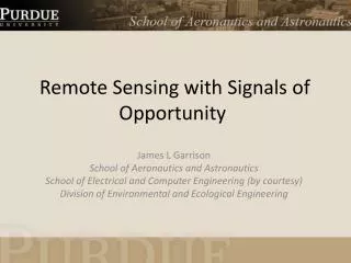
ANISOTROPY IN OCEAN SCATTERING OF BISTATIC RADAR USING SIGNALS OF OPPORTUNITY. Rashmi Shah*, Dr. James Garrison*, Dr. Michael Grant** *School of Aeronautics and Astronautics, Purdue University **NASA Langley Research Center. Outline. Background Previous Work Overview of XM Radio System

E N D
ANISOTROPY IN OCEAN SCATTERING OF BISTATIC RADAR USING SIGNALS OFOPPORTUNITY RashmiShah*, Dr. James Garrison*, Dr. Michael Grant** *School of Aeronautics and Astronautics, Purdue University **NASA Langley Research Center IGARSS – Vancouver, Canada - July 24-29, 2011
Outline • Background • Previous Work • Overview of XM Radio System • Motivation • Objective • Airborne Experiment • Data Processing • Results • Summary and Future Work IGARSS – Vancouver, Canada - July 24-29, 2011
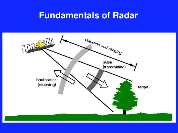
Previous Work • Global Navigation Satellite System Reflectometry (GNSS-R) • First demonstration of remote sensing with “signals of opportunity” • Retrieval of ocean surface roughness, wind speed, soil moisture, and ice • 15 years of development: airborne and space (UK-DMC) • GNSS-R enabled by use of known pseudo-random noise (PRN) code • Digital Communication Signals Reflectometry • Expand methods to other “signals of opportunity” • Demonstrated with XM digital radio • Commercial satellite radio system in the US IGARSS – Vancouver, Canada - July 24-29, 2011
Motivation IGARSS – Vancouver, Canada - July 24-29, 2011 • Why Digital Communication Signals? • Multiple frequency bands: Different sensitivity • Higher transmitted power: Better accuracy • Located in geostationary orbit: Fixed geometry • Challenge: • No a priori knowledge of data bits • Hypothesis: • Data bits are long, random, uncorrelated stream • Hypothesis verified using XM digital radio signals (S-band) [Shah, et al, IGARSS 2010]
XM System • Two active geostationary satellites IGARSS – Vancouver, Canada - July 24-29, 2011 • Rhythm (115oW) • Elevation: 31.3o • Azimuth: 234.4o • Blues (85oW) • Elevation: 41.6o • Azimuth: 196.4o
Objective Quantify retrieval anisotropy between two satellites at different azimuth Examine potential to retrieve wind direction from this effect IGARSS – Vancouver, Canada - July 24-29, 2011
Airborne Experiment IGARSS – Vancouver, Canada - July 24-29, 2011
Waveforms • Sampling Frequency • 8MHz • Coherent Integration • 10ms • Incoherent Integration • 1sec Altitude of the aircraft: 3,471 meters (11,400 feet) Cross-correlation of direct and reflected signals IGARSS – Vancouver, Canada - July 24-29, 2011
Data Processing • Two-step estimation process [Garrison 2003] • First step: • Isotropic normal PDF assumed • Nonlinear least squares estimation = Mean Square Slope (MSS) = Scale factor (remove variation in signal power) =Delay offset (adjust small uncertainties in delay) • Independent estimate for each satellite IGARSS – Vancouver, Canada - July 24-29, 2011
Data Processing Rhythm: 0.0076 (6 m/s) Blues: 0.0098 (7.2 m/s) Chesapeake Lighthouse (CHLV2): 7.5 m/s (MSS = 0.0010) IGARSS – Vancouver, Canada - July 24-29, 2011
Data Processing • Second Step: • 2-D normal slope PDF • Model fit to both satellites simultaneously • Isotropic MSS su2+sc2 fixed to average from first step • Cross-/up-wind ratio (sc/su) fixed to 0.85 • Principal axis α of PDF varied to minimize residuals • Wind direction with respect to North IGARSS – Vancouver, Canada - July 24-29, 2011
Results Minimum residual found at θW = 57o IGARSS – Vancouver, Canada - July 24-29, 2011
Results • CHLV2 reported that the wind direction was 28o • Discrepancy can be due to: • CHLV2 & measurement location separated by 80km • Closest Buoy (44014) not reporting data • Azimuth separation between satellites only 38o - may give reduced sensitivity IGARSS – Vancouver, Canada - July 24-29, 2011
Summary and Future Work • Summary • Anisotropy gives equivalent wind speed difference of 1.2m/s • Wind direction may contribute to this effect • Difference between principal axis of wind speed was 29o • Future Work • Single model fit to both satellites data • Find better surface truth values: • Model runs at measurement location IGARSS – Vancouver, Canada - July 24-29, 2011
Thank You! IGARSS – Vancouver, Canada - July 24-29, 2011
References J.L. Garrison, A. Komjathy, V.U. Zavorotny, and S.J. Katzberg, “Wind speed measurement using forward scattered GPS signals,” IEEE Transactions on Geoscience and Remote Sensing, vol. 40(1), pp. 50–65, 2002. J.L. Garrison, S.J. Katzberg, and M.I. Hill, “Effect of sea roughness on bistatically scattered range coded signals from the Global Positioning System,” Geophys. Res. Lett, vol. 25(13), pp. 2257–2260, 1998. E. Cardellach and A. Rius, “A new technique to sense non-Gaussian features of the sea surface from L-band bi-static GNSS reflections,” Remote Sensing of Environment, vol. 112, no. 6, pp. 2927 – 2937, 2008. R. Shah, J.L. Garrison, M.S. Grant, and S.J. Katzberg, Analysis of correlation properties of digital satellite signals and their applicability in bistaticremote sensing,” Proceedings of the 2010 IEEE International Geoscience and Remote Sensing Symposium, pp. 4114–4117, July 2010. J.L. Garrison, “Anisotropy in reflected GPS measurements of ocean winds,” Proceedings of the 2003 IEEE International Geoscience and Remote Sensing Symposium, pp. 4480–4482, July 2003. IGARSS – Vancouver, Canada - July 24-29, 2011
BACKUP AND EXTRAS IGARSS – Vancouver, Canada - July 24-29, 2011
Previous Work • Waveform generated by cross-correlating ocean-reflected signals with locally generated pseudorandom code was used • Methods used: • Matched Filters (Garrison, et al 1998) • Nonlinear least squares parameter estimation (Garrison, et al 2002) • Discretized approximation of the full-slope PDF(Caedellach, et al 2008) IGARSS – Vancouver, Canada - July 24-29, 2011
Glistening Zone Rhythm: Semi-major = 4.76km, Semi-minor = 2.47km Blues: Semi-major = 5.40km, Semi-minor = 2.80km IGARSS – Vancouver, CANADA- July 21-24, 2010
Airborne Experiment: Geometry Experiment conducted: 02-July-2010 in Piper Navajo Experiment time period: 07:51AM EDT - 09:19AM EDT IGARSS – Vancouver, Canada - July 24-29, 2011