Download

1 / 21
210 likes | 378 Views
Speed Sensing. Team: Kicking Asphalt Ryan Dempsey - Team Leader Jordan Severo - Hardware Specialist Matt Bonaddio – Software Specialist John Donofrio - Assistant Hardware Mike Bichsel - Assistant Software. Presentation Overview. Problem Statement Hardware Topics

E N D
Speed Sensing Team: Kicking Asphalt Ryan Dempsey - Team Leader Jordan Severo - Hardware Specialist Matt Bonaddio – Software Specialist John Donofrio - Assistant Hardware Mike Bichsel - Assistant Software
Presentation Overview • Problem Statement • Hardware Topics • Sensor Specifications • Sensor Mounting • Sensor Wiring • Calculating Distance • Software Topics • Calculating Speed • TPM Initialization • Source Code • References • Q&A
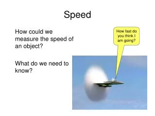
Problem Statement • Continuous tracking of the Smartcar’s real time speed. • Units of centimeters/second. • Measuring distance between two optical encoder holes (rising edges)
Sensor Wiring (GP1A75 OPIC Photointerrupter) • Pin 1 – VCC – 5V DC {Yellow} • Pin 2 – Vout – to MCU (pin PTF2) {Red} • Pin 3 – GND {Black} *Connect a by-pass capacitor from Vin to GND >0.01uF
Sensor Mounting Tight on bottom and top Eliminates rubbing
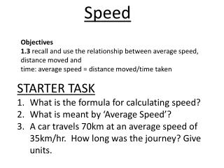
Calculating Distance • Wheel Diameter=5.4864cm • Circumference=17.2359cm • 1 full revolution is 8 pulses • With each pulse the car covers 2.15cm
Calculating Speed • Distance travelled (2.15 cm) per logic high • TPM1C4’s input capture mode will trigger an interrupt at every rising edge • Access TPM1C4V to record the time at which the event occurred
Calculating Speed • We need the time between two captures • TachPeriod is a global variable • TachPeriod = (currentcnt-lastcnt)/3 • Dividing by 3 accounts for the 3Mhz clock • Results in a TachPeriod in microseconds
Calculating Speed • Speed = distance / time • currentspeed = 2.15 cm / TachPeriod • But… • That would be in cm per microsecond! • We need cm per second
Calculating Speed • currentspeed = x • currentspeed = = • # define CMPUS 2150000 • currentspeed = CMPUS/TachPeriod
TPM Initialization • TPM1C4SC register is used for control and status of the TPM module • The bits of concern are • CHnF – Interrupt Flag Bit • CHnIE – Interrupt Enable Bit • MSnB – Mode Select Bit • MSnA – Mode Select Bit • ELSnB - Edge Level Select Bit • ELSnA – Edge Level Select Bit • 0b01000100 Will be the value which needs assigned
TPM Initialization – 0b01000100 • The sensor will be producing a rising edge on the detection of a hole • For input capture on rising edge configure TPM as shown 0 1 0 0 0 1 0 0
Source Code • New Constant • Global Variables • Initialization #define CMPUS 2150000 //2.15 cm per reading, multiplied by 1e6 to convert to second Global Variables: int TachPeriod = 0; //Time from one hole to the next on speed sensor int currentspeed = 0; //global result of getSpeed() function Initialization: TPM1C4SC = 0b01000100 //Enables interrupts and input capture mode(rising edge)
Source CodeISR Routine – Tach_isr( void ) interrupt 75 void Tach_isr(void) //interrupt vector 75 is for TPM1 Ch.4 { static int lastcnt = 0; //Previous count at last tach reading int currentcnt = 0; //Initialize current count currentcnt = TPM1C4V; //take current readings from value register TPM1C4SC &= 0x7F; // acknowledge the interrupt TPM1C4SC_CH4IE = 1; // re-enable for the next interrupt TachPeriod=( currentcnt – lastcnt ) / 3; //Calculate period between tac readings //3 accounts for the 3 megahertz bus clock lastcnt = currentcnt; //update the last count }
Source CodeFunction do_speed() - Calculates the speed given a period int do_speed( int TachPeriod ) //TachPeriod argument { if( TachPeriod != 0 ) //to prevent division by zero { currentspeed = (CMPUS/TachPeriod); //calc speed in cm per second return currentspeed; //return result } return 0; //else return 0 }
Source Codemain() nsf++; // only update every 100 main loops do_speed(TachPeriod); // calculate the speed from period if((currentspeed > 0) && (nsf % 100 == 0)) // only if the current speed is valid { LCD_clear(); // clear the display sprintf(s, "%u", currentspeed); // create the string for the LCD LCD_line(0, s); // display current speed on LCD }
Summary • Hardware Topics • Sensor wiring – 5v supply to yellow • Sensor Mounting – tight screws • Software Topics • Calculating Distance – CMPUS/TachPeriod • TPM Initialization – TPM1C4SC = 0b01000100 • Avoid divide by 0! • Q&A
References • Huang, Han-Way. HCS12/9S12: An Introduction to Software and Hardware Interfacing. 2nd ed. Delmar, Cengage Learning, 2010. • GP1A75 OPIC Photointerrupter Datasheet. Sharp Corporation. 2005. Web. http://www.aet.calu.edu/~jsumey/CET360/smartcar/datasheets/GP1A75E.pdf • MCF51JM128 ColdFire Integrated Microcontroller Reference Manual. 2. Freescale Semiconductor, Inc., 2009. Web.http://www.aet.calu.edu/ftp/cet/360/resources/Coldfire/MCF51JM128-RefManual-v2.pdf. • Sumey, Jeff. “CET Microprocessor Engineering.” California University of Pennsylvania. Web. 18 Feb 2014. http://aet.calu.edu/~jsumey.