Download
1 / 132
1.32k likes | 1.46k Views
TEAM 2. Remote Control Car. Team #2: Total Resources. 500 Man hours $500 or key part availability for material and prototyping LPI-Sean (BSEE) LSD-Russ (BSEE) LPM-Adam (BSEE) LRM-Brad (BSEE) LMM-Barry (BSEE). Team #2 Project.

E N D
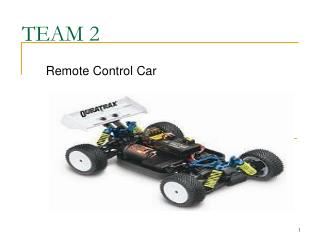
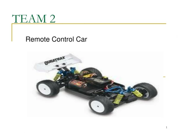
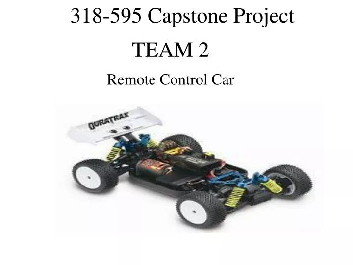
TEAM 2 Remote Control Car
Team #2: Total Resources • 500 Man hours • $500 or key part availability for material and prototyping • LPI-Sean (BSEE) • LSD-Russ (BSEE) • LPM-Adam (BSEE) • LRM-Brad (BSEE) • LMM-Barry (BSEE)
Team #2 Project • Our project is a remote control car, that can display battery life speed and direction, and can turn on the lights at the flip of a switch or if it gets dark. • The benefit to the user would be a better remote control car • There are similar types of products, however we are the only one that has all of these features. • Our product would fall under the consumer industry • Picture from http://www.rccaraction.com/
Project Features • The remote control car has a two-way antenna that can transmit to and receive data from the car. • Control of the car will come from the controller. • The car can turn its lights on and off manually, and automatically if it gets dark enough. • The display will tell us the speed and direction of the car, and the battery life remaining.
Team #2: Project 1Block Assignment Digital RF Trans / Rec Sean [4] RF Trans / Rec Sean [4] Digital Digital Digital Power Supply Brad [2] Ctrlr Processor Brad [3] Car Processor Russ [6] On Car Sensing Adam [8] Digital Analog Analog Electromechanical Control Russ[7] Digital Signal Input & Display Barry [1] Power Source Sean [5] PCB 1, power supply will be connected to all blocks PCB 2, power supply will be connected to all blocks
Competitor’s Slide RequirementUnits to Specify • Traxxus, Tra5510 • $600 million, website • $200 • World-Wide • 6 yr. old to adult, boys • Home, toy • $80 / unit • $20 / unit • 6 million / yr • Competitors • Market Size • Average List Price • Market Geography • Market Demography • Intended Application • Material Cost • Manufacturing Cost • Annual Volume
System - Std Reqs: Production RequirementUnits to Specify • 12,000 cm3 • 18,000 cm3 • 2 Kilograms • 5 • 200 cm2 Total • 50 G force • Max Volume • Shipping Container Size • Max Mass • Max # of PC Bds • Max PCB Circuit Area • Max Shock
System - Std Reqs: Mfg & Life Cycle RequirementUnits to Specify • 200 Total Parts • 100 Unique Parts • $80 (Parts+Mfg=Product Cost) • $20 (Parts+Mfg=Product Cost) • 3 yrs • 6 months • Repair • Max Parts Count • Max Unique Parts Count • Parts/Mat $ Allocation • Asm/Test $ Allocation • Product Life, Reliability • Full Warranty Period • Service Strategy
System - Std Reqs: Enviroment RequirementUnits to Specify • 10-60 Co • 10-90% non-condensing • 0-3000 Meters • 0-80Co • 10-90% non-condensing • 0-3000 Meters • 1 year • Min Oper Temp Range • Min Oper Humidity Range • Min Oper Alt or Press Range • Min Storage Temp Range • Min Storage Humidity Range • Min Storage Alt or Press Range • Max Storage Duration
System - Std Reqs: Power Interfaces RequirementUnits to Specify • Min Oper Voltage Range • Max Power Consumption • Max Energy Consumption • Car Battery Chemistry • Car Battery Capacity • Controller Battery Pack • Controller Display Segments • Controller Accuracy • Modes of Operation • 5-9.0 V and 5-15.0 V • 18.0 Watts Total • 6000 mAH Total • Nimh • 6000 mA-Hrs • i.e. AA 1.5V • 10 bars • ⅛ battery life • On/Off
System – Perf Reqs: Display • Mono Color • 150mm x 70mm • 1 meter • Any • 20 Total Char/Row, 4 Total Rows • 20cm x 10cm • LED • LCD Display: • Display size: • Max. Display Distance: • Viewing Environment: • Display Char Matrix: • Display Size: • Display Illumination:
System – Perf Reqs: Operator I/F Inputs RequirementDefinition • 40 dB • 1% • 80 • .25V • .005s • 300m • Min SNR • Max THD • Min Power Gain • Max Error Voltage • Max Delay • Min EM Transmission Distance
System – Perf Reqs: Lights & Speed RequirementDefinition • ON/OFF/AUTO • None • ± 3 mph • 200 ms • 0-40 mph • 8 Directional Units • 200 ms • 0-5V logic levels • 200 ms • Lights • Power Saving Modes • Accuracy • Updates • Speed Range • Accuracy • Response Time • Input/Output • Updates
System – Perf Reqs: Safety Standards • We will be using the standards UL 2202 1.5, UL2111 1.5, UL 1977, Cispr 61000-6-3, EMC 61000-4-2, EMC 61000-4-4, and EMC 61000-4-5 in order to make sure that our product is safe. • These standards insure that there is no risk to the user from the product and vice versa. • The EMC standards protect our product from ESD and power surges.
From Lab 1 Manhours-500 Material $500 ~2% for design ~86% for detailed design ~2% for verification ~10% for documentation From Lab 3 Manhours-1702 Material $1031 These values may be off due to overlapping of projects. Estimation Slide
Product Assembly • We will try to use as many SMT components as we can. • We will use a Perfboard to connect all components.
Signal Input Designed by: Barry Gentz
Team #2: Project 1Block Assignment Digital RF Trans / Rec Sean [4] RF Trans / Rec Sean [4] Digital Digital Digital Power Supply Brad [2] Ctrlr Processor Brad [3] Car Processor Russ [6] On Car Sensing Adam [8] Digital Analog Analog Electromechanical Control Russ[7] Digital Signal Input & Display Barry [1] Power Source Sean [5] PCB 1, power supply will be connected to all blocks PCB 2, power supply will be connected to all blocks
Block 1 • Signal input consists of 2 potentiometers, a switch, ESD protection, filtering, and logic gates.
Block 1 - Std Reqs: Env & Safety RequirementUnits to Specify • 10-60 Co • 10-90% non-condensing • 0-3000 Meters • 0-80Co • 10-90% non-condensing • 0-3000 Meters • 1 year • Min Oper Temp Range • Min Oper Humidity Range • Min Oper Alt or Press Range • Min Storage Temp Range • Min Storage Humidity Range • Min Storage Alt or Press Range • Max Storage Duration
Block 1 - Std Reqs: Power Interfaces RequirementUnits to Specify • Energy Source List • Source Connection List • Operating Voltage Range • Max Power Consumption • Max Energy Consumption • Max Potential • Power Supply • Permanent/Temp • 4.9-5.1 V • 18.0 Watts • 1000 mAH • 9 V
Block 1 - Std Reqs: Mechanical RequirementUnits to Specify • Tyco • 1 • 100 cm2 Total • 50 G force • Elec I/F Connector(s) • Max # of PC Bds • Max PCB Circuit Area • Max Shock
Block 1- Std Reqs: Mfg & Life Cycle RequirementUnits to Specify • 25 Total Parts • 12 Unique Parts • $125 • $50 • 3 yrs • 6 months • Dispose • Dispose or Repair • Max Parts Count • Max Unique Parts Count • Parts/Mat $ Allocation • Asm/Test $ Allocation • Product Life, Reliability • Full Warranty Period • Product Disposition • Service Strategy
Block 1 – Perf Reqs: Operator I/F Inputs RequirementDefinition • 60 dB • 1% • 80 • .25V • Min SNR • Max THD • Min Power Gain • Max Error Voltage
Block 1– Perf Reqs: Mech Interfaces / Safety • Male pin • .005 Amps • .004 s • .005 Amps • .004 s • .005 Amps • .004 s • .005 Amps • Connectors • Signal 1 Max Current Limit • Signal 1 Max Trip Time • Signal 2 Max Current Limit • Signal 2 Max Trip Time • Signal 3 Max Current Limit • Signal 3 Max Trip Time
Signal Input Speed Analog Direction Processor Analog Lights Digital Power ( 5V )
Sub-Block Design Analysis Plan 5K Pot ESD LP Filter Processor 5K Pot ESD LP Filter Switch ESD De-Bounce Digital Signal Analog Signal Power Signal Power
Signal Input: Signal Type Digital Analog
Task-Resource Estimate Summary Resources (after 10/11) • Time 200 hours • Money $125 max
Digital Block DFM - DC Drive Analysis Table • Vxx in Volts, Ixx in mA • Source Currents Listed as Negative • Std = Standard, OC = Open Collector/Drain, TS = Tristate, ST – Schmitt Trigger
Testing • Functional tests are needed after assembly which include : • Turning on the controller/car and running through dir/speed operations, turning on/off lights, running in dark environment.
Power Supply Designed by: Brad LaCount
Team #2: Project 1Block Assignment Digital RF Trans / Rec Sean [4] RF Trans / Rec Sean [4] Digital Digital Digital Power Supply Brad [2] Ctrlr Processor Brad [3] Car Processor Russ [6] On Car Sensing Adam [8] Digital Analog Analog Electromechanical Control Russ[7] Digital Signal Input & Display Barry [1] Power Source Sean [5] PCB 1, power supply will be connected to all blocks PCB 2, power supply will be connected to all blocks
Power Supply Block Consists of 10 AA style batteries and a low-dropout voltage reference supplying 5V to the controller components.
Block 2 - Std Reqs: Env & Safety RequirementUnits to Specify • 10-60 Co • 10-90% non-condensing • 0-3000 Meters • 0-80Co • 10-90% non-condensing • 0-3000 Meters • 1 year • Min Oper Temp Range • Min Oper Humidity Range • Min Oper Alt or Press Range • Min Storage Temp Range • Min Storage Humidity Range • Min Storage Alt or Press Range • Max Storage Duration
Block 2 - Std Reqs: Power Interfaces RequirementUnits to Specify • Energy Source List • Source Connection List • Operating Voltage Range • Max Power Consumption • Max Energy Consumption • Battery • Temporary • 5.7-8.0 V • 18.0 Watts • 2800 mAH
Block 2 - Std Reqs: Mechanical RequirementUnits to Specify • Tyco • 1 • 20 cm2 Total • 50 G force • Elec I/F Connector(s) • Max # of PC Bds • Max PCB Circuit Area • Max Shock
Block 2- Std Reqs: Mfg & Life Cycle RequirementUnits to Specify • 30 Total Parts • 5 Unique Parts • $10 (Parts+Mfg=Product Cost) • $50 (Parts+Mfg=Product Cost) • 3 yrs • 6 months • Dispose • Dispose or Repair • Max Parts Count • Max Unique Parts Count • Parts/Mat $ Allocation • Asm/Test $ Allocation • Product Life, Reliability • Full Warranty Period • Product Disposition • Service Strategy
Block 2 – Perf Reqs: Power Input(s) • 10 AA 1.5V Controller • Battery Pack
Block 2 – Perf Reqs: Electrical Interfaces Electrical Signal ReqDirection • Output • Power Signal
Block 2 – Perf Reqs: Operator I/F Inputs RequirementDefinition • 60 dB • 1% • 80 • .25V • Min SNR • Max THD • Min Power Gain • Max Error Voltage
Block 2– Perf Reqs: Mech Interfaces / Safety RequirementDefinition • Male pin, Battery tray • 9V • Connectors • Max Potential