Download
1 / 21
210 likes | 371 Views
Rapid Prototyping Technologies. Wei-Ren Ng Department of Electrical and Computer Engineering, University of Arizona. Introduction. Rapid prototyping (RP) is a new manufacturing technique.

E N D
Rapid Prototyping Technologies Wei-Ren Ng Department of Electrical and Computer Engineering, University of Arizona
Introduction • Rapid prototyping (RP) is a new manufacturing technique. • allows for fast fabrication of computer models designed with three-dimension (3D) computer aided design (CAD) software. • RP is used in a wide variety of industries, from shoe to car manufacturers. • Allows for fast realizations of ideas into functioning prototypes, shortening the design time • Lead towards successful final products
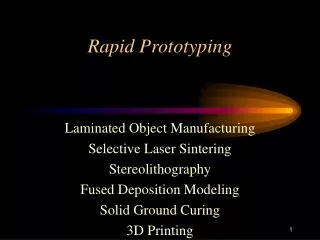
Introduction • Two general types: • Additive • Subtractive, • Subtractive type RP or traditional tooling manufacturing • a technique in which material is removed from a solid piece of material until the desired design remains. • Examples: • computer numerical control (CNC) • electric discharge machining (EDM). • Additive type RP is the opposite of subtractive type RP. • Instead of removing material, material is added layer upon layer to build up the desired design • Examples: • fused deposition modeling (FDM) • selective Laser Sintering (SLS)
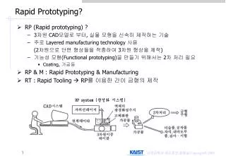
Design Steps • Process: • Design CAD model • Export as STL • 2D slices • printing • Different types of RP technologies, all of them require the 3D CAD model’s Stereolithography file for fabrication.
Stereolithography (STL) File Format • Stereolithography or Standard Tessellation Language (STL) file format. • only describes the surface geometry of a 3D CAD model. • No information on the color, texture or material. • The surface geometry is described with triangular facets. • Each triangle facets uses a set of Cartesian coordinates to describe its three vertices and the surface normal vector using a right-hand rule for ordering.
Exporting STL from Solidworks • File Save as Change ‘Save as type’ to .STL • Select ‘Options’ for more advance export options. • Can select to export the STL as Binary or ASCII file format in millimeter, centimeter, meter, inches or feet depending on the unit used in the CAD model.
STL File Format Tolerancing • Example of different STL tolerance
Additive Rapid Prototyping Systems • The different types of additive RP technologies can be categorized into three types: • Liquid based (SLA and Inkjet based Printing) • Solid based (FDM) • Powder based (SLS) • Common components: • Print tray • Embedded computer for control systems • Curing process – UV or laser • Client computer – convert STL to 2D print slices
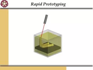
Liquid based Additive Rapid Prototyping • StereoLithography Apparatus (SLA)
Liquid based Additive Rapid Prototyping • INKJET BASED
Solid based Additive Rapid Prototyping • Fused Deposition Modeling FDM
Powder based Additive Rapid Prototyping • Selective Laser Sintering (SLS)
Optomechanical Applications 3D CAD design considerations: • RP fabrication tolerances – fitting and alignment • Optical fine adjustment ability • Stiffness of material to support heavy optical devices • Fasteners • Spacing • Adhesion
Optomechanical examples • Zemax exported .STP file in Solidworks • Design integrated optomechanical parts around optics
Optomechanical examples • Spectral image classifier
Optomechanical examples • Adjustable camera mount
Conclusion • Advantages: • Fast and inexpensive method of prototyping design ideas • Allows for an integrated optomechanical design • Multiple design iterations to finalize design • Physical validation of design • Disadvantages: • Resolution not as fine as traditional machining (millimeter to sub-millimeter resolution) • Surface flatness is rough (dependant of material and type of RP)