Download
1 / 36
360 likes | 534 Views
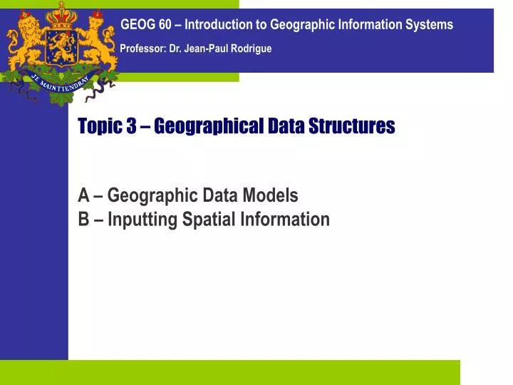
Topic 3 – Geographical Data Structures. A – Geographic Data Models B – Inputting Spatial Information. A. Geographic Data Models. 1. Raster Representation 2. Vector Representation 3. The ArcView Shapefile Model. 1. Spatial Objects. Definition Delimited geographic areas.

E N D
Topic 3 – Geographical Data Structures A – Geographic Data Models B – Inputting Spatial Information
A Geographic Data Models • 1. Raster Representation • 2. Vector Representation • 3. The ArcView Shapefile Model
1 Spatial Objects • Definition • Delimited geographic areas. • Ex. park, golf course, wildlife reserve. • Associated attributes. • Attributes are qualities or characteristics of spatial objects. • Ex. census data, types of vegetation, heights or depths. • Types of geographical delimitation • Three conventional delimitations. • Points, lines and polygons. Grass, 1 feet Shrubs, 6 feet Forest, 25 feet
Representation 1 Raster Representation • Issue • A model for a computer to represent real geographical elements as graphical elements (on screen or on paper). • Two models of representation possible: • Raster (grid-based) • Vector (line-based)
1 Raster Representation • Cellular organization • Divides space in a series of units. • Each unit is generally similar in size to another. • Grid cells is the most common raster representation. • Features are divided into cellular arrays. • Coordinate (X,Y) is assigned to each cell, as well as a value. • Allows for registration with geographic reference system. • JPEG, GIF, BMP and TIF are raster formats. • Tessellation • Geometric shapes that can completely cover an area. • Squares / Rectangles. • Triangles. • Hexagons.
Column Row 1 Raster Representation Point Line Real world Value =0 =1 =2 =3 Raster Grid Area Triangles Hexagons
1 Raster Representation 700 meters • Advantages • Easy to conceptualize. • Overlay operations are easy. • A two-dimensional array forms a coverage. • The problem of resolution • For a small grid: • Coarse resolution but limited storage space. • For a large grid: • Fine resolution but large storage space. Size = 7x7x4 = 196 Cell = 10 m x 10 m = 100 m2 Size = 10x10x4 = 400 Cell = 7 m x 7 m = 49 m2
1 The Mixed Pixel Problem
2 Vector Representation • Concept • Assumes that space is continuous, rather than discrete. • Infinite (in theory) set of coordinates. • Points • Spatial objects with no area but can have attached attributes. • A single set of coordinates (X and Y) in a coordinate space. • Lines • Spatial object made up of connected points (nodes). • Have no width. • Polygon • Closed areas that can be made up of a circuit of line segments. • Line segments that make up a portion of a polygon. Point (X,Y) (X2,Y2) Line (X4,Y4) (X3,Y3) (X5,Y5) (X,Y) (X,Y) (X2,Y2) Polygon (X5,Y5) (X3,Y3) (X4,Y4)
Node 1 Node 2 Node 3 2 3 1 Arc C Arc D Arc E Arc B Node 5 5 Node 4 Arc H 4 Arc F Arc G Arc A Node 8 8 6 Node 6 Arc I Node 7 Arc J 7 Node X Y Arc From To 1 2 3 4 5 6 7 8 12 22 53 24 5 36 17 38 4 16 42 17 9 43 21 44 A B C D E F G H I J 6 4 1 2 5 4 7 3 8 7 4 1 2 3 2 5 5 8 7 6 2 Vector Representation
2 3 1 C D A E B 5 C H 4 F G A B 8 6 I J 7 Poly # of arcs Arc list A B C 4 4 5 B,C,E,F A,F,G,J E,D,H,I,G 2 Vector Representation
Point Table Line Table Poly. Table Attrib. Table Pt. ID X Y Ln. ID Pt. 1 Pt. 2 Pol. ID Ln. ID Pol. ID Attrib. 1 2 3 4 5 ... 24.5 24.8 27.8 30.1 14.2 ... 27.4 24.1 22.5 29.9 30.1 ... 35 36 37 38 39 ... 1 4 6 2 8 ... 3 2 8 10 11 ... 74 74 74 75 75 ... 38 35 29 28 42 ... 74 75 76 77 78 ... 104.2 100.1 105.7 102.7 106.1 ... 2 Vector Representation Relational Links
2 GIS Vector Models – 3 Major Models Unique identifier Coordinate and Topological files Attribute tables Relational database Hybrid (Features) - Relational join – (Attributes) Relational database Integrated Element – Class – Attribute Object store Object-Oriented
3 The ArcView Shapefile Model • Format • Hybrid data model. • Store spatial information in a vector format. • Sequential list of features. • Less processing intensive (faster drawing time). • Two-dimensional (x,y) and three-dimensional (x,y,z) features supported. • Each shapefile represent one shape type. • Point, Polyline, and Polygon are the most common. • Three major components: • Main file (*.shp): Store the list of geographical features. • Database file (*.dbf): Store the attributes in a table. • Index file (*.shx): Links the database and geographical features.
3 The ArcView Shapefile Model Main file (*.shp) Index file (*.shx) dBase table (*.dbf) a a b b c c d d
3 The ArcView Shapefile Model geometry object identifier (optional) geometry tracking field (optional) geom id shp_len type surface width lanes name 101 102 103 104 105 ... 4507.4 3491.1 2321.8 682.9 1279.1 ... 2 1 3 5 4 ... asphalt concrete asphalt gravel asphalt ... 85.3 45.1 75.9 35.2 60.3 ... 4 2 4 2 4 ... abc def ghi jkl mno ... Predefined fields custom fields
C Inputting Spatial Information • 1. The Input Subsystem • 2. Choosing What to Input • 3. Editing Vector Objects
1 Input Subsystem • Digitizing • Most difficult and time consuming task in mapping and GIS. • Takes about 75% of the time in a mapping project. • About 75% of the costs of operating a GIS system. • Digitizing and errors • Since digitizing is very time consuming, you must get it right on the first time. • Error correction is excessively long and costly. • The larger the file, the bigger the number of potential errors. • Each model, raster or vector, requires special digitizing equipment.
1 Input Subsystem • Mouse • The mouse is the most basic input system. • A rolling ball with two sensors, one of X, one for Y. • It continuously sends a set of X,Y coordinates to the CPU. Buttons are sending interrupts to the CPU. • By itself, it cannot be used to encode mapping information, but it is suitable for tracing. X,Y Pointer
1 Input Subsystem • Tracing and digitizing • Tracing is a form of digitizing. • Mainly imply using a scanned image. • Easier for less experienced users. • Precision is limited to the resolution of the scanned image.
1 Input Subsystem • Digitizer • Table containing a matrix of very small cables. • A mouse-like device, often called a puck (cursor), moves over the table. • Creates an electromagnetic field disruption on the grid, the center of which is the X,Y coordinate. • One of the most precise digitizing technique. • Varies according to: • Stability: Tendency of coordinates to change with temperature. • Repeatability: With the same location, are the X,Ys exact? • Linearity: Keeping up with movements of the cursor. • Resolution: The smallest unit or measure it can handle. • Skew: Differences between variation of Xs and Ys.
1 Input Subsystem • Scanner • An horizontal light makes a pass and each line is read by a photoelectric cell (like a photocopy machine). • Resolution: • Number of pixels per units of surface the cell can read. • 1,200 DPI (Dots per inch) is common. • Color depth: • Number of different colors the cell can read. • 1-bit only supports B&W, 4-bit 16 colors (or shades of gray), 8-bit 256 colors and 12-bit 16.7 million colors. • Two types: • Drum scanners (rotating drum), • Flat-bed scanners.
2 Choosing What to Input • Some Rules • Find what are your goals. • Digitize the information you really need: • Most base maps contain a lot of information. • Try to choose a conventional source of spatial data. • Use the level of accuracy corresponding to your task: • High levels of accuracy equal high levels of diminishing returns. • Input data as separate themes: • Each theme should be specific. • Each theme has a specific geographic feature (point, line or polygon).
2 Choosing What to Input Type of Feature Information Points Lines Polygons Streets Store Locations Parks Highways Themes
Not enough Too Many Good Solution 2 Choosing What to Input • How Much to Input • Choosing the right amount of information to encode is difficult. • Depends on the level of accuracy.
2 Base Map (Air Photograph)
2 Digitizing Major Roads and the Hydrography
2 Digitizing Lots
2 Final Product
3 Editing Vector Objects • Points • Simply changing the coordinate. • Dragging and dropping the most common. • Lines • Changing the coordinate of one or more points. • Splitting a line in two. • Merging lines. • Polygons • Changing the coordinate of one or more points (the last point is also the first point). • Splitting a polygon in two. • Using a boundary to draw another polygon. • Merging polygons. • Creating an island in a polygon. • Creating an intersection.
Intersection 3 Editing Vector Objects Splitting a line Moving a point (vertex) Merging lines Line B Line A
Polygon A Polygon B 3 Editing Vector Objects Moving a point (vertex) Splitting a polygon
3 Editing Vector Objects Merging polygons Using a boundary
3 Editing Vector Objects Creating an island Creating an intersection
3 Editing Vector Objects • Snapping • Make a vertex take the coordinates of a reference. • Spanning tolerance defines the “search space”. • Avoid overshoots and undershoots for lines. • Avoid gaps and overlaps for polygons. • Snap to Vertex • Snaps the next vertex to the nearest vertex in an existing line or polygon. • Snap to Boundary • Snaps the next vertex to the nearest line segment in an existing line or polygon boundary.
3 Editing Vector Objects • Snap to Intersection • Snaps the next vertex to the nearest node common to two or more lines or polygons. • Snap to Endpoint • Snaps the next vertex to the nearest endpoint of an existing line. • For lines only.