Download
1 / 14
190 likes | 895 Views
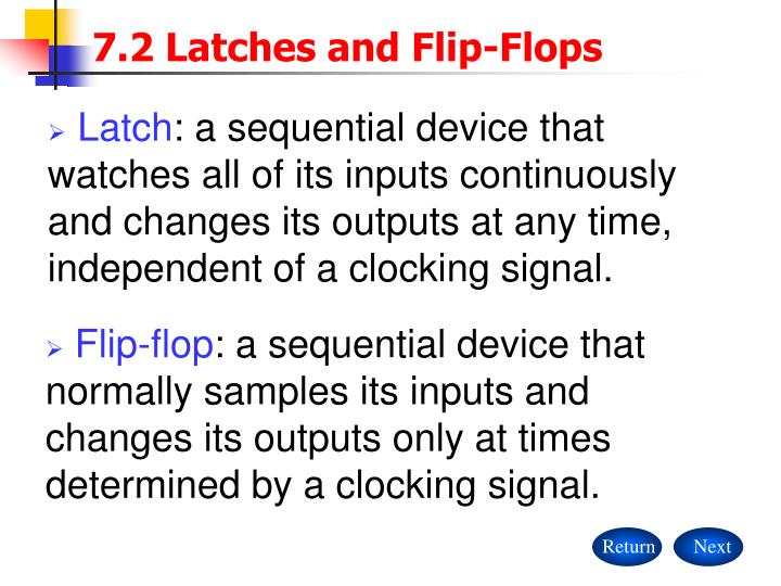
Return. Next. 7.2 Latches and Flip-Flops. Latch : a sequential device that watches all of its inputs continuously and changes its outputs at any time, independent of a clocking signal.

E N D
Return Next 7.2 Latches and Flip-Flops • Latch: a sequential device that watches all of its inputs continuously and changes its outputs at any time, independent of a clocking signal. • Flip-flop: a sequential device that normally samples its inputs and changes its outputs only at times determined by a clocking signal.
S R Qn+1 Qn+1 R Q 0 0 0 1 1 0 1 1 Qn Qn 0 1 1 0 0* 0* S Q Return Back Next 7.2 Latches and Flip-Flops • 7.2.1 S-R Latch Next state 2. Function table 1. Logic diagram Reset Primary state Metastable Set
S R Q S Q Q R Q Return Back Next 7.2 Latches and Flip-Flops 3. Functional behavior 4. Characteristic equation
S R Q tpLH(SQ) tpw(min) tpHL(RQ) Return Back Next 7.2 Latches and Flip-Flops 5. Timing diagram • Propagation delay: tpLH(SQ), tpHL(RQ) • Minimum pulse width: tpw(min)
7.2.2 S-R Latch Q S S R Qn+1 Qn+1 0 0 0 1 1 0 1 1 1* 1* 1 0 0 1 Qn Qn Q R Return Back Next 7.2 Latches and Flip-Flops
S Q R Q S Q R Q S S Q C R Q Q C Q R Return Back Next 7.2 Latches and Flip-Flops • 7.2.3 S-R Latch with Enable • Functional behavior (See P538 Figure 7-11) • Logic symbol
C D Qn+1 Qn+1 D Q 1 0 1 1 0 x 0 1 1 0 Q Q C Q Return Back Next 7.2 Latches and Flip-Flops • 7.2.4 D Latch S-R latchs are useful in control application, a D (data) latch may be used to store bits of information. • Characteristic equation The D latch eliminates the SR=1 problem of the S-R latch, but dose not eliminate the metastability problem.(P539)
master slave QM D D Q C Q D Q C Q Q Q CLK Return Back Next 7.2 Latches and Flip-Flops • 7.2.5 Edge-Triggered D Latch • A positive-edge-triggeredD flip-flop combines a pair of D latches, to create a circuit that samples its D input and changes its Q and QN outputs only at the rising edge of a controlling CLK signal.
D D CLK Qn+1 Qn+1 CLK 0 1 x 0 x 1 0 1 1 0 Qn Qn Qn Qn QM D Q CLK Q Q Return Back Next 7.2 Latches and Flip-Flops The master is open all the while that CLK is 0, The slave is open all the while that CLK is 1. Positive-edge-triggered
CLK D Q tpLH(CQ) tpHL(CQ) thold tsetup <tsetup Return Back Next 7.2 Latches and Flip-Flops • Timing diagram
master slave QM D D Q CLK Q D Q C Q D Q C Q Q Q CLK D Q EN CLK Q PR D Q CLK Q CLR Return Back Next 7.2 Latches and Flip-Flops • Negative-edge-triggeredD flip-flop Negative-edge-triggered • Asynchronous inputs (preset and clear inputs) • Edge-triggeredD flip-flop with enable
master slave S QM Q S Q C R Q S Q C R Q R QN C Return Back Next 7.2 Latches and Flip-Flops • 7.2.6 Master/Slave S-R Flip-Flop • Master/Slave S-R Flip-Flop output value depends on input values not just at the falling edge, but during the entire interval in which C is 1 prior to the falling edge.
S R C Qn+1 Qn+1 x x 0 0 0 0 1 1 0 1 1 Qn Qn Qn Qn 0 1 1 0 Undef. Undef. S Q C R Q Return Back Next 7.2 Latches and Flip-Flops Master/slave flip-flope • 7.2.7 Master/Slave J-K Flip-Flop (P546 Figure 7-26, Figure 7-27)
Return Back 7.2 Latches and Flip-Flops • 7.2.8 Edge-Triggered J-K Flip-Flop (P547~548 Figure 7-28, Figure 7-29) • 7.2.9 T Flip-Flop (P549 Figure 7-31 ~7-33)