Download
1 / 1
10 likes | 188 Views
TAP: Token-Based Adaptive Power Gating Andrew B. Kahng, Seokhyeong Kang, Tajana S. Rosing, and Richard Strong UC San Diego. enable_few. m[0]. m[0-9]. m[1]. UCSD CSE. m[9]. enable_rest. Core Power Gating. Power-gating controller. Overview. Motivation

E N D
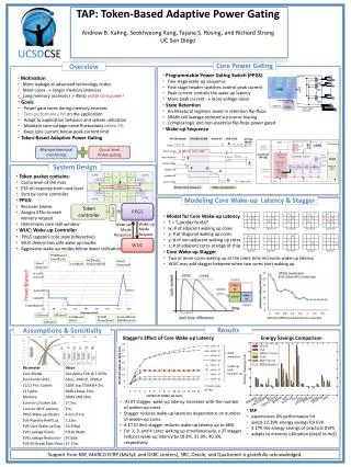
TAP: Token-Based Adaptive Power Gating Andrew B. Kahng, Seokhyeong Kang, Tajana S. Rosing, and Richard Strong UC San Diego enable_few m[0] m[0-9] m[1] UCSDCSE m[9] enable_rest Core Power Gating Power-gating controller Overview • Motivation • More leakage at advanced technology nodes • More cores longer memory latencies • Long memory accesses ( > 45ns) waste core power! • Goals • Power gate cores during memory accesses • Zero performance hit on the application • Adapt to application behavior and system utilization • Maintain core-voltage noise fluctuations below 5% • Keep core current below peak-current limit • Token-Based Adaptive Power Gating • Programmable Power Gating Switch (PPGS) • Two-stage wake-up sequence • First-stage header switches control peak current • Peak current controls the wake-up latency • More peak current more voltage noise • State Retention • Architectural registers saved in retention flip-flops • SRAM-cell leakage reduced via source biasing • Complex logic and non-essential flip-flops power gated • Wake-up Sequence Microarchitecturalmonitoring Circuit level Power gating System Design • Token packet contains: • Cache level of the miss • ETA of response from next level • Sent by cache controller • PPGS: • Receives tokens • Assigns ETAs to each memory request • Determines core stall window • WUC: Wake-up Controller • PPGS registers core state (idle/active) • WUC determines safe wake-up modes • Aggressive wake-up modes follow lower utilization Modeling Core Wake-up Latency & Stagger PPGS Tokencontroller Token • Model for Core Wake-up Latency • T = T0(w+βx+Υy+δz)α • w: # of adjacent waking up cores • x: # of diagonal waking up cores • y: # of non-adjacent waking up cores • z: # of adjacent cores at edge of chip • Core Wake-up Stagger • Two or more cores waking up at the same time increases wake-up latency • WUC may add stagger between when two cores start waking up Wake-up Mode Request Wake-up Mode Response WUC Assumptions & Sensitivity Results Stagger’s Effect of Core Wake-up Latency Energy Savings Comparison • At 0T stagger, wake-up latency increases with the number of woken-up cores • Stagger reduces wake-up latencies dependence on number of woken-up cores. • A 1T (0.3ns) stagger reduces wake-up latency up to 66% • For 2, 3, and 4 cores waking up simultaneously, a 3T stagger reduces wake-up latency by 18.8%, 31.9%, 40.3%, respectively • TAP • experiences 0% performance hit • yields 22.39% energy savings for EV6 • 5.17X the energy savings of practical DVFS • adapts to memory utilization (bzip2vsmcf) Support fromNSF, MARCO FCRP (MuSyC and GSRC centers), SRC, Oracle, and Qualcommis gratefully acknowledged.