Download
1 / 37
380 likes | 575 Views
Ash Recovery At Kingston Fossil Plant Kingston, Tennessee. Presented by: Tim Harrington, P.E. - Hard Hat Services. Site History. Site is on the upper end of the Watts Bar Reservoir just north of Interstate 40. The coal-fired generating station was constructed in the 1950’s.

E N D
Ash RecoveryAt Kingston Fossil PlantKingston, Tennessee Presented by: Tim Harrington, P.E. - Hard Hat Services
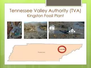
Site History • Site is on the upper end of the Watts Bar Reservoir just north of Interstate 40. • The coal-fired generating station was constructed in the 1950’s. • The generating station draws cooling water from the Emory River and discharges to the Clinch River which in turn enters the Tennessee River. • Slack water from the Watts Bar Dam envelopes the mouth of both the Clinch and the Emory River. • Prior to the ash spill the main channel of the Emory River at the Site is approximately 30-feet deep.
Overall Site Location Map River Emory Ash Storage Kingston Power Plant Clinch River
Fly Ash Storage History • Originally, ash was sluicedwet from the plant to a basin constructed in the Watts Bar Reservoir • The basin is contained by a clay dike that is raised three times to eventually impound 60-feet thickness of ash • Starting in the 1980’s, accumulating ash was dredged and stored in an engineered storage cell constructed on top of the filled basin • By late 2008, the storage cell reached 60-feet height and covered approximately 90 acres
AerialFall 2008 Prior to Ash Pond Release Bottom ash removed in sluice trench Fly ash settled in Ash Pond Water quality obtained in stilling basin Ash pond solids hydraulically dredged to ash storage cell EmoryRiver Ash Storage Cell Ash Pond Stilling Basin Sluice Trench Plant Water Intake
Ash Release • Early morning of December 22, 2008 a dikefailure near the northwest corner of ash storage results in static liquefaction of nearly 2/3 of the stored ash • The flowing ash water mixture flows into the Emory River moving both upstream and downstream • When the flow stopped, the main channel of the river was filled with ash • The Emory flows around the ash in a shallow area of the Watts Bar Impoundment
AerialDecember 23, 2008Day After Ash Spill Main channel filled with over 30 feet of ash Emory River flowing around the ash in shallow impounded water of Watts Bar Reservoir Ash Storage Cell
What is Fly Ash? • Fly ash is the fine residue from the burning of coal that escapes with the combustion gas and is removed by air treatment equipment • With bottom ash it is 10% by weight of the coal at Kingston • The majority of fly ash is within the size range of 100 to 1 micron (fine sand and silt particle size) • The particles are spherical with some particles forming as hollow spheres known as cenospheres • Because of the cenospheres the solid specific gravity may be lower than for earth minerals (as low as 2.0)
Fly Ash Magnified2000x Fly Ash consists primarily of oxides of silicon, aluminum iron and calcium (85-90% by weight). Magnesium, potassium, sodium titanium, and sulfur oxides make up most of the remaining weight with traces of heavy metals . Specific gravity of fly ash at Kingston in the 2.2 -2.4 range Source: Federal Highway Administration
Grain Size Curve SAND Sizes SILT sizes Grain Size of Ash in Dredge Pipeline from Pilot Test
Purpose of Ash Removal • Time Critical Removal was to open Main Thalweg of the Emory River • Non-Time Critical work on land and in embayments separated from Time Critical by a landside rock berm. • Opening river channel to approximate original contours was goal of removal • It was recognized that further dredgingmay be required in later stages of the ash recovery after completion of the Time Critical Removal
Emory River Dredging Segments Upland Rock Berm Segment 1: Ash Filled Full Channel Segment 2: Full Channel but With Some Flotation Water Segment 3: Underwater Rock Berm to PreventFurther Downstream Movement. Segment 4 & 5: Thinning Ash Thickness with Flotation Water
Time Line for Progress • It was considered time critical that the main channel be open by no later than Spring 2010. • Avoid impact from the Spring flood season of 2010. • Besides the logistics of dredging and dewatering the ash, the logistics of removing the ash from the site had to be resolved to complete the removal. • It was estimated that the time critical work involved 3.0 million cubic yards of ash.
Ash Recovery by Hydraulic Dredging • Experience at the site was already good with hydraulic dredging for building the ash storage cell • It was believed that the ash would settle out quickly in a rim ditch removal method as was used to build the ash storage cell • The production rate using mechanical dredging was slower with the same level of manpower and equipment • The existing ash pond and sluice ditch were available for hydraulic operation
Pilot Test Operation • Pilot testing of concept to hydraulically dredge to a Rim Ditch started late March 2009 and ran through July 2009 • Trans Ash of Cincinnati Ohio operated (3) Ellicott 370 10-inch pump swinging ladder dredges with booster pumps • Rim Ditch 1,800-ft. long, 40-ft. wide and 10-ft. deep • Solids delivered to Rim Ditch at 4,000 dry tons per day • Total flow in Rim Ditch of 8,300 gpm (10 MGD)
Trans Ash Dredge Dredges had twenty foot, twenty-five foot and thirty foot ladders
Rim DitchandSluice Trench Sluice Trench Rim Ditch prior to start of Pilot Dredging Rim Ditch Ball Field Area
Results of Pilot Test • Average percent dry solids to the ditch 8.4% • Flocculent Settling Rate 14 in/hour • Solids Content after 12 hours of quiescent settling 65% • Rim Ditch removal rate of 90% when the flow was under 10,000 gpm • With higher flows more solids to the Sluice Trench • Constant agitation of the Rim Ditch by backhoe results in a thickened solids content of 30-35% in the water column of the ditch.
Time Versus Concentration 65% Solids
Dredging Results • 10-inch pump dredges were too small to complete the work within the timeline goals • Substantial problems with plugging from trees and other debris • Ash is very abrasive and results in heavy maintenance impact on operation. • Three 10-inch dredges moved on average 4,000 cubic yards per day • Problems with dredges from fast river currents • At end of pilot 375,000 cubic yards removed
Full Scale Dredging Operation • Competitive bidding to dredge at full-scale operation defined as completing 1.5 million cubic yards to open the main channel by February 28, 2010. • Required production rate of approximately 12,000 cubic yards per day 6-days per week • Competitive bidding for the work with Sevenson Environmental selected for the work. • Dredging equipment initially on site was one 20-inch cutterhead dredge and one 14-inch cutterhead dredge • Later supplemented with a 16-inch cutterhead dredge
20-Inch Dredge Subcontracted bySevensontoL.W. Matteson
20-Inch Dredge Cutter Head Approximately 4.5-ft. diameter
14-Inch Dredge Ellicott 670 owned by Sevenson
Full Scale Operations • 20-inch River Dredge average 470 cubic yards per hour • 16-inch dredge average 230 cubic yards per hour • 14-inch dredge average 160 cubic yards per hour • Rim ditch is operated at twice its hydraulic capacity (on average 20 MGD) • Substantial solids carryover to sluice trench and ash pond
Observations • Rim Ditch operated at 20 MGD 100% above its hydraulic capacity determined during the pilot test • Efficiency of the Rim Ditch was reduced fromthe pilot operation and the fly ash pond was required to store ash • With the use of a coagulent, the stilling basin continued to produce acceptable water for discharge (permit limit average TSS of 29 ppm) • Using a dredge to remove ash from the fly ash pond and cycle back to the Rim Ditch provided little improvement of performance
Performance In Fly Ash Pond P1 Sample With Depth
Performance In Fly Ash Pond P2 Sample With Depth
Summary of Full Scale Performance • Ash Pond filled at rate of approximately 4,000 yd3/day (approximately 1/3 of the daily in-river dredge volume) • February 1, 2010 1.5 million cubic yards removed under full scale dredging • Ash Pond removal was undertaken in January 2010 to develop new pond capacity to complete Emory River removal goal • Goal of opening river channel is obtained with very little reserve capacity in ash pond
Thank YoutoJacobs Engineering Group, Inc.&Tennessee Valley AuthorityforPermission to PresentatWEDA 2010Midwest Chapter Annual Meeting