Download
1 / 20
220 likes | 443 Views
SCD Visio ToolBox. SAS designer functions overview. MidTechnology AS 26.10.2013. Currently there are a lot of solutions allow you to create different types of drawings. AutoCAD and Microstation are the most popular of them.

E N D
SCD Visio ToolBox SAS designer functions overview MidTechnology AS 26.10.2013
Currently there are a lot of solutions allow you to create different types of drawings. AutoCAD and Microstation are the most popular of them. But the main disadvantage is, that you should have some skills of using this programs and time to modify or create drawings. Using of this products for SCD diagrams is very time-consuming. Visio based tools are designed to make drawing SCD diagrams easier and faster. It provides additional features for design of SAS system. SCD Tools for Visio
SAS designer functions overview SCD Visio stencils- Main Shapes- Sequence Symbols - Equipment Connecting Shapes Propagation ManagerCause & Effect ReportInterNodeReportXML Export and ImportXML Document StructureXML Element Structure Diagram navigation and searchSystem and Subsystem HidingDiagram Checks SCD Tools for Visio
“Main Shapes” Stencil contains SCD related shapes, like Function Blocks and Software Functions. SCD Visio Stencils
“Sequence Symbols” Stencil contains shapes for designing of SCD Sequence flow diagrams. SCD Visio Stencils
“Equipment” Stencil contains some Equipment shapes. Additional Equipment shapes, depending on specific project, can be added by users. Any other Visio stencils can be used in combination with SCD Visio ToolBox stencils. SCD Visio Stencils
When You connect different SCD shapes, using General Signal (located in “SCD Main Shapes” stencil), Connection Manager window appears, providing list of possible inputs/outputs of shape. List content depends on type of shape, You are connecting. For example, if You want to connect ingoing signal to “SBV” type function block, Connection Manager will list all possible inputs to SBV block, based on NORSOK standard: Connecting Shapes
Propagation manager helps correctly connect itemsfrom different SAS subsystems. It is launched, when you connect shapes, and checks assigned subsystems (PCS, PSD, ESD, F&G). If one of shapes/signals hasn’t any SAS subsystem assigned, Propagation Manager will automatically assign SAS subsystem, assigned to connected shape or signal. Propagation Manager • If both connected shapes/signals have SAS subsystem assigned, Propagation Manager provides to user choices to resolve situation.
User can choose effects for Function Blocks (FB). Possible effects list is generated from shapes, connected to outputs. To select effects of FB, right click on Cause FB and select effects from “possible effects” list. Cause & Effect Report After selecting effects for FB’s, Cause & Effect Report can be exported to Excel format (C&E Report button is located on ribbon).
InterNode Report includes connections between different SAS nodes. It is exported to Excel format. InterNode Report
Advantages: • Could be used for diagram converting between different CAD applications and versions • Input for Control System generation tools • SCD integration with other tools XML Export and Import
<shapes> <FunctionalBlocks> < FunctionalBlock> { FB properties } </ FunctionalBlock> { Other functional blocks } </ FunctionalBlocks> <SoftwareFunctions> { Software functions } </SoftwareFunctions> <HardwareFunctions> { Hardware functions } </HardwareFunctions> <Uncategorized> { Other items } </Uncategorized> </shapes> XML Document Structure
<FunctionalBlockuid="{1E6507C1-BDD5-4160-B2CB-4290BEC625B3}" name="20HZV0008"> <props> <prop name="Typical or Mode" /> <prop name="Function Template Type">SBV</prop> <prop name="Node">56</prop> <prop name="System (Tag)">20</prop> <prop name="Instrumentation Identification (Tag)">HZV</prop> <prop name="Sequence Number (Tag)">0008</prop> <prop name="Comment" /> <prop name="SAS System">P</prop> <prop name="EffectList" /> <prop name="Shape Type">FunctionBlock</prop> </props> <pos left="13,779" top="11,889" right="14,724" bottom="11,417" /> <connects> <In> <connect input="LSL" uid="{51EC6DE7-289D-4D5B-9D9D-A1F8EE96EECE}">S</connect> </In> <Out> <connect output="Y" uid="{68F64938-18A4-4A31-8B4B-3FB2AAE6247B}" /> <connect output="BCL" uid="{3D26486A-F9FA-4BCD-84CE-68040D86B502}">20PIC0012.LSL</connect> </Out> <Undirected /> </connects> </FunctionalBlock> XML Element Structure
When user wants to navigate to specified shape, he can use Search function. It will focus drawing on selected shape. Diagram navigation and search
Diagram Explorer is used for fast navigation through shapes. It contains structured list of all functional blocks. Shape on diagram is focused, when element in Diagram Explorer is double clicked. Diagram navigation and search
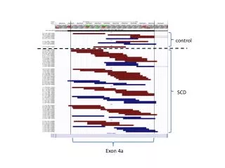
Layer Hiding Manager’s tree view contains all subsystems/nodes, presented on diagram. User can check/uncheck subsystems or nodes. Unchecked nodes are shadowed on diagram. Subsystem Hiding
Diagram can be checked for broken connections. Check function provides list of not connected connections. Diagram Checks
C&E Linear, matrix • Alarm management TRXXXX IEC • SIF SIL module - SIL SIF allocation (from SRS) - SIL SIF PFD calculation • Functional block editor Future functions When connecting functional blocks, user is assisted by Connection Manager. User can choose needed input/output from list. List content is based on functional block typical (MA, CA, SBV, etc.)Functional blocks editor will provide possibilities to create, modify and save user own typical.
Free for education purpose 14 days free for evaluation purpose End user license 1-10 with annual support agreement Corporate license with support agreement, for more than 10 users Additional technical support in case of implementation users own function, shapes and SCD block in our program code. For any question send mail to scd@midt.no License policy