Download
1 / 13
160 likes | 323 Views
Chapter1. Circuit Concept. Network: The interconnection of two or more simple circuit elements is called an electric network. Circuit: If a network contains at least one close path, it is termed an electric circuit.

E N D
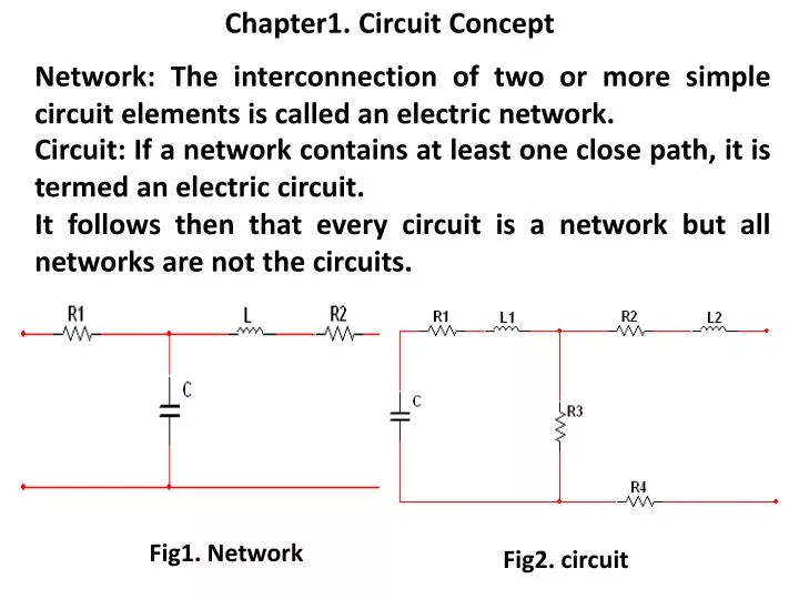
Chapter1. Circuit Concept Network: The interconnection of two or more simple circuit elements is called an electric network. Circuit: If a network contains at least one close path, it is termed an electric circuit. It follows then that every circuit is a network but all networks are not the circuits. Fig1. Network Fig2. circuit
Chapter1. Circuit Concept Active Network: a network containing at least one active element such as independent voltage or current source is called an active network. Fig3. Active Network
Chapter1. Circuit Concept Passive Network: a network which does not contain any active element is called a passive network. Fig3. Passive Networks
Chapter1. Circuit Concept Branch of the network: A circuit element in a network may be called the branch of a network. Sometimes , all those elements which are connected in series such that identically the same current flows through them can be said to constitute a branch.
Chapter1. Circuit Concept Node: A point in a network where two or more circuit elements meet is termed as node. In fig4 1, 2 & 4 are nodes. Principal Node : A point in a network where three or more circuit elements meet is called a principal node. In Fig4. 2 & 4 are principal nodes. Terminal Node : Terminal of a branch not connected anywhere is called a terminal node. In Fig4. 3 & 5 are terminal nodes. Fig4. For understanding of different nodes
Chapter1. Circuit Concept Loop: A close electrical path in the network is called a loop. Mesh : A close electrical path which does not enclose any other close path inside it is called a mesh. Thus all meshes are the loops, but not all loops are the meshes. In Fig.5 ABEFA & BCDEB are meshes & loops, whereas ABCDEFA is a loop but not a mesh. Fig5. For understanding of mesh & loop
Chapter1. Circuit Concept CLASSIFICATION OF NETWORKS Classification of the networks depends upon The kind of elements of which the network is composed of & on the basis of their properties In terms of the general properties of its responses to excitation applied to its input terminals
Chapter1. Circuit Concept • LINEAR NETWORKS & LINEARITY • In a linear network, the voltage & current relationship is • described by a linear equation. • Suppose network is under relaxed condition i.e the initial • condition is zero and an excitation e1(t) is applied for which the • response is c1(t) & for excitation e2(t), the response is c2(t). • Then the network is classified as linear if for excitation • e1(t)+ e2(t), the response is c1(t)+ c2(t). This shows that that a • linearity follows super position theorem. • The validity of the principal of superposition means that the • presence of one excitation does not affect the responses due to • the other excitations and there are no interactions among the • responses of different excitations in the network. • A network is linear if it satisfies the principle of superposition.
Chapter1. Circuit Concept • TIME-INVARIENT & TIME-VARIENT NETWORK • A network is said to be time-invariant if the network produces • the same response to a given excitation irrespective of time of • application of excitation. • If the response to an excitation e(t) is c(t), then in time-invariant • network, the excitation e(t+t1) will produce a response c(t+t1) • where t1 is any time. • This implies that the values of network components are constant • at all times and do not change with time in a time-invariant • network. • If the parameters vary with time in a network, the network is • called a time-varying network.
Chapter1. Circuit Concept • RECIPROCITY PROPERTY OF THE NETWORK • Some networks have the property that the response produced at • one point of the network by an excitation acting at another point • is invariant if the positions of excitation and response are • interchanged. (with the proper polarities of the excitation & the • response functions) If V1(t) = V2(t) Then I1(t) = I2(t) It is called a reciprocal network. 2 1 NETWORK I2(t) V1(t) 2’ 1’ 2 1 NETWORK I1(t) V2(t) 2’ 1’ Fig6. For understanding Reciprocal Network
Chapter1. Circuit Concept • LUMPED & DISTRIBUTED NETWORK • Many devices in electrical system are distributed in space e.g • transmission lines, windings of transformers or generators are • distributed in a way. Whenever these devices are energized, the • effect is not experienced by the line length or winding lengths • instantly because of finite velocity of electric signals. However, if • interest in steady state or terminal quantity, it is sufficient to • assume the parameters lumped rather then distributed. • Sometimes, when we are interested in the intermediate values • and point to point variation of electric signals , we talk true • nature of these devices i.e distributed nature. • Otherwise, we assume the parameters to be lumped.
Chapter1. Circuit Concept • UNILATERAL & BILATERAL NETWORK • In bilateral element the voltage current relationship is the same • irrespective of direction of flow of current in it e.g resistance, inductance, capacitance. • A unilateral element has different voltage-current relations for • two possible directions of flow of current i.e diode, rectifier etc.
Chapter1. Circuit Concept • ACTIVE & PASSIVE COMPONENTS OF NETWORK • Energy source (Voltage or Current sources) are active elements, • capable of delivering energy to some external device. • The passive elements are those which are capable only of • receiving energy or power. • Some passive elements like inductors & capacitors are capable of • storing a finite amount of energy & return it later to an external • device. • More specifically, an active element is capable of delivering an • average power greater than zero to some external device over an • infinite time interval. For example, ideal sources are active • elements. • The passive element is defined as one that cannot supply • average power that is greater than zero over an infinite time • interval e.g. resistor, inductor, capacitor etc. fall in this category.