Download
1 / 25
2.17k likes | 9.96k Views
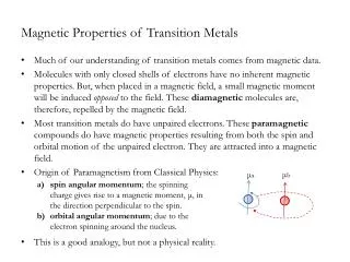
Magnetic Properties of Transition Metals. Much of our understanding of transition metals comes from magnetic data.

E N D
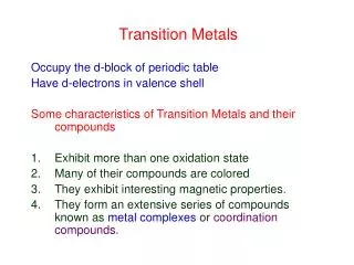
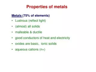
Magnetic Properties of Transition Metals • Much of our understanding of transition metals comes from magnetic data. • Molecules with only closed shells of electrons have no inherent magnetic properties. But, when placed in a magnetic field, a small magnetic moment will be induced opposed to the field. These diamagnetic molecules are, therefore, repelled by the magnetic field. • Most transition metals do have unpaired electrons. These paramagnetic compounds do have magnetic properties resulting from both the spin and orbital motion of the unpaired electron. They are attracted into a magnetic field. • Origin of Paramagnetism from Classical Physics: • This is a good analogy, but not a physical reality. μb μa • spin angular momentum; the spinning charge gives rise to a magnetic moment, μ, in the direction perpendicular to the spin. • orbital angular momentum; due to the electron spinning around the nucleus.
Magnetic Moment • The magnetic moment of a single electron, μs, is given (according to wave mechanics) by μs = g√ s (s + 1) B.M. • Also, μs = √ n (n + 2) B.M. where n = number of unpaired electrons. • For example, Ti+3 (d1) μs = 2√ ½ (½ + 1) = 1.73 B.M. • For a multielectron case, μs = g√ S (S + 1) B.M. where S = total spin quantum number • For example, Mn+2 (d5) h.s., μs = 2√ 5/2 (5/2 + 1) = 5.92 B.M. where g = gyromagnetic ratio ≈ 2 s = absolute value of the spin quantum number B.M. = bohr-magneton (eh/4πmc) — — — — — S = ½+½+½+½+½ = 5/2
Theoretical Versus Experimental Moments • Look at Ion, S, μs, and observed moments. • Notice that for many ions, the μs and the μobs values are fairly consistent, for others, the μs is not even close. • This is because μs is a “spin-only” momentum. • For some transition metals, there is an orbital angular momentum contribution. • The magnetic moment for these situations is given by: μS+L = √4S(S + 1) + L(L + 1) μL μS where L = total orbital angular momentum quantum number.
Theoretical Versus Experimental Moments • Examples: • Compare to μS+L on Table. • Notice that μobs values are still less than μS+L; this is because μS+L assumes a free ion (i.e. a metal with no ligands). • With ligands the orbital motion is “quenched”. — — — — — L = 2 + 1 + 0 + -1 + -2 Ti+3 d1 L = 2 note numbering and order of filling — — — — — L = 2 + 1 + 0 + -1 + -2 V+3 d2 L = 2 + 1 = 3 — — — — — L = 2 + 1 + 0 + -1 + -2 Co+2 d7 L = 2 + 1 + 0 = 3 — — — — — L = 2 + 1 + 0 + -1 + -2 Mn+2 d5 L = 2 + 1 + 0 + -1 + -2 = 0
Instrumentation/Experimentation • Don’t measure μobs directly, but do measure magnetic susceptibility, Χm, and then calculate magnetic moment: μobs = 2.828 √ Xm ● T(K) B.M. Remember: μobs = √ n (n + 2) B.M. where n = number of unpaired electrons. when n = 1 μ = 1.73 B.M. n = 2 μ = 2.83 B.M. n = 3 μ = 3.87 B.M. n = 4 μ = 4.90 B.M. n = 5 μ = 5.93 B.M.
Using Magnetic Susceptibility Data • The following compounds have the indicated Xm values at 300K. Describe the structure of each. • [NiF6]-2 Xm = 0.00 B.M. • Ni(PET3)2Cl2Xm = 0.00 B.M. • Ni(Ph3AsO)2Cl2Xm = 0.0065 B.M. • A chromium complex has Xm = 0.0100 B.M.; what is its oxidation state? ─ ─ ─ ─ ─ ─ ─ ─ ─ ─ 6-coordinate Ni+4 d6 could be either high spin or low spin μobs = 4-coordinate Ni+2 d8 could be either tetrahedral or sq. planar μobs = ─ ─ ─ ─ ─ ─ ─ ─ ─ ─ 4-coordinate Ni+2 d8 could be either tetrahedral or sq. planar μobs = μobs =
Term Symbols S = ½ + ½ = 1 L = 1 + 0 = 1 — — — 1 0 -1 • Let’s look at the p2 case. • Is this the only way to arrange the electrons and still have L = 1? • No. • How about p3 with L = 0? • Notice that whatever the initial value of S, there are 2S + 1 possible orientations of the resultant spin angular momentum vector ; called the multiplicity of the state. • Going back to p2: are the above the only three ways to arrange electrons in these orbitals? plus others… • No, but which of these are degenerate and which is the ground state? 3 possible S values not necessarily ground states S = 0 S = -1 — — — — — — S = 3/2 S = 1/2 S = - 1/2 S = - 3/2 — — — — — — — — — — — — 1 0 -1 L = 1 + 0 + -1 = 0 4 possible S values — — — — — —
Term Symbols • It will be convenient to somehow relate the angular momentum, the spin multiplicity, and the energy for each of the possible electronic states. • This is done with Term Symbols, which take the form: • Instead of using numbers for L, we use letters. • Go back and look at “Magnetic Moments” Table. • Again, want to determine degeneracies and gs of the different orientations, but first must determine all possible states. Done systematically. 2S+1L where S = spin orbital momentum 2S + 1 = multiplicity L = total angular momentum L = 0 1 2 3 4 designated: S P D F G same as for l’s, but in CAPS does NOT indicate orbital type S = 1 L = 1 e.g. p2 so, the term symbol for this state = 3P pronounced “triplet-P” — — — 1 0 -1 e.g. S = ½ and L = 4 2G “doublet-G” state S = 3/2 and L = 2 4D “quartet-D” state
Determining Term Symbols — • Ignore filled shells and orbitals as they are singularly degenerate. • so only interested in partially filled orbitals. • Nomenclature: • each set of electrons and their orientations is called a microstate. • for spins, instead of using ms = +½ or -½, just use + or ─. • for angular momentum, will use ml = 1, 0, -1, etcetera. • can’t do (1+, 1+) due toPauli exclusion principle; (1+, 0─) & (0─, 1+) redundant. • although for 2p13p1 microstates (1+, 1+) allowed; (1+, 0─) & (0─, 1+) not redundant. — — — e.g. for the p3 microstate: electron # 1: ms = +½ and ml = 1 electron # 2: ms = ─½ and ml = 0 electron # 1: ms = +½ and ml = -1 1 0 -1 expressed in shorthand as: (1+, 0─, -1+) — — — e.g. the p2 microstate: expressed in shorthand as: (1+, 0─). 1 0 -1
Determining Term Symbols • Determine the number of unique microstates. • first, for p-orbitals take 6! 6 x 5 x 4 x 3 x 2 x 1 or for d-orbitals, 10! 10 x 9 x 8 x 7 x 6 x 5 x 4 x 3 x 2 x 1 • but truncate list by the number of electrons (n) • then divide by n! • Bookkeeping • NOT a physical reality, just a systematic method. • set up table of possible microstates (see next slide for p2; 15 possible microstates). n = 2 6 x 5 x 4 x 3 x 2 x 1 2! 6 x 5 e.g. 2p2 # unique microstates = ───── = 15 2 x 1 6 x 5 x 4 e.g. 2p3 # unique microstates = ───── = 20 3 x 2 x 1
Table of Possible Microstates for p2 Σms 1 0 -1 — — — not possible note symmetry in table 1 0 -1 Σml 2 1 0 -1 -2 — — — ml = 1 + 1 =2 ms = +½ + (-½) = 0 1 0 -1 — — — ml = 1 + 0 = 1 ms = -½ + (-½) = -1 1 0 -1 — — — ml = -1 + 0 = -1 ms = +½ + (-½) = 0 1 0 -1
Table of Possible Microstates for p2 • Bookkeeping • find the maximum Σml value that has the maximum Σms value. • here Σml max = 2 Σmsmax =0, or L = 2 and S = 0. • the term symbol for this is 1D. • The degeneracy for any term symbol = multiplicity(2L + 1) • for 1D = 1(2(2) + 1) =5; this means that five of the microstates belong to 1D. • cross out five microstates on table; begin with max and go down; no more than one from each box. • find the new maximum Σml value that has the maximum Σms value. Σms 1 0 -1 Σml 2 1 0 -1 -2 (1+, 1─) (0+, 0─) (-1+, -1─) (1+, 0─) (1─, 0+) (1+, -1─) (1─, -1+) (-1+, 0─) (-1─, 0+) (1+, 0+) (1─, 0─) (1+, 0+) (1─, 0─) (-1+, 0+) (-1─, 0─)
Table of Possible Microstates for p2 • Bookkeeping • find the new maximum Σml value that has the maximum Σms value. • here Σml max = 1 Σmsmax =1, or L = 1 and S = 1. • the term symbol for this is 3P. • The degeneracy for this term symbol = 3(2(1) + 1) =9; this means that nine of the microstates belong to 3P. • cross out nine microstates on table. • repeat until all microstates crossed out. • final microstate; L= 0 and S = 0, which is 1S (singularly degenerate). • list all term symbols found: 1D, 3P and 1S. Note sum of the degeneracies: 5 + 9 + 1 = 15. Σms 1 0 -1 Σml 2 1 0 -1 -2 (1+, 1─) (0+, 0─) (-1+, -1─) (1+, 0─) (1─, 0+) (1+, -1─) (1─, -1+) (-1+, 0─) (-1─, 0+) (1+, 0+) (1─, 0─) (1+, 0+) (1─, 0─) (-1+, 0+) (-1─, 0─)
Determining Term Symbols • Bookkeeping • use Hund’s Rules to determine ground state. • state with maximum multiplicity is the ground state. • if more than one state has the same maximum multiplicity, the ground state is one with the maximum L value. • compare to handout “Multiple Terms” • Helpful hint: “holes” can be treated like unpaired electrons. • for example, rather than treating this like p5, treat it like p1. therefore, for p2 g.s. is 3P then 1D then 1S — — — p1 ≡ p5 d1 ≡ d9 p2 ≡ p4 d2 ≡ d8 p3 d3 ≡ d7 d4 ≡ d6 d5
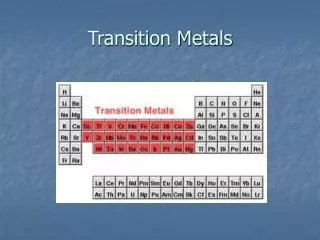
Term Symbols in an Octahedral Field • The Term Symbols determined above were for a spherically symmetrical field. • What happens when we put the d-orbitals into an octahedral field? • the full degeneracy is lost; split is according to Table. • T ≡ triply degenerate; E ≡ doubly degenerate; A ≡ singularly degenerate. • simplest case is d1. • Note: These are NOT orbitals; each is a degenerate state. • For a d9 complex in an octahedral field, the energy level diagram is obtained by inverting that of the d1 complex. • The g.s. for a d9 is doubly degenerate; excited is triply degenerate. • Remember: these aren’t orbitals, but designations of degeneracy. ─ ─ ─ ─ ─ ─ ─ ─ ─ ─ 2Eg 2T2g ─ ─ ─ ─ ─ each has a multiplicity of 2 (here spin up, spin down) increasing 10Dq — — — — — 2D ─ ─ ─ ─ ─ ─ ─ ─ ─ ─ ─ ─ ─ ─ ─ in a spherical field degeneracy = 2(2(2) +1) = 10 in an octahedral field 2T2g 2Eg
Orgel Diagrams • We can combine the d1 and d9 Oh diagrams into a single Orgel Diagram. • Remember that d1 Td splitting is just the opposite of d1 Oh, so d1 Td and d9 Oh have similar Orgel Diagrams; same with d9 Td and d1 Oh. • Note that gerade (g) and ungerade (u) designations apply only to Oh case. Eg d9 Oh d1 Oh T2g d1 Td d9 Td T2g → Eg transition Eg → T2g transition T2g Eg ←increasing 10Dq 0 increasing 10Dq→
Orgel Diagrams • What happens when more than one electron is present? • For example, d2, with the spherically symmetric terms 3F, 3P, 1G, 1D, and 1S. • As before, in the Oh field the spherically symmetrical terms are “split” into terms of lower symmetry. • In d2, the 3F term (the ground state) is split into 3A2g, 3T1g and 3T2g terms; the excited state, 3P, becomes a 3T1g term. • Why are we ignoring the 1G, 1D, and 1S terms? In understanding the electronic spectra, only the triplet states need to be considered because the ground state (3F) is a triplet. Transitions from the ground state to these other states would involve not only an energy transition, but also a “flip” of one of the electron spins. Such a transition is said to be multiplicity forbidden. • Remember that these terms represent sets of degenerate electron configurations. ─ ─ ─ ─ ─ ─ ─ ─ ─ ─ ─ ─ ─ ─ ─ forbidden ─ ─ ─ ─ ─ allowed
Orgel Diagrams ─ ─ ─ ─ ─ d8 Oh d2 Oh 3A2g (eg2) d2 Td d8 Td 3T1g • First look at splitting of the ground state, 3F, term as we move from a spherically symmetric to octahedral (or tetrahedral) field. 3P 3F 3T2g (t2g1eg1) ─ ─ ─ ─ ─ ─ ─ ─ ─ ─ ─ ─ ─ ─ ─ 3T2g ─ ─ ─ ─ ─ ─ ─ ─ ─ ─ ─ ─ ─ ─ ─ 3A2g 3T1g(t2g2) ←increasing 10Dq 0 increasing 10Dq→
Orgel Diagrams ─ ─ ─ ─ ─ d8 Oh d2 Oh 3A2g (eg2) d2 Td d8 Td 3T1g ─ ─ ─ ─ ─ ─ ─ ─ ─ ─ ─ ─ ─ ─ ─ 3T1g (t2g1eg1) 3P 3F 3T1g 3T2g (t2g1eg1) ─ ─ ─ ─ ─ ─ ─ ─ ─ ─ ─ ─ ─ ─ ─ 3T2g ─ ─ ─ ─ ─ ─ ─ ─ ─ ─ ─ ─ ─ ─ ─ 3A2g 3T1g(t2g2) ←increasing 10Dq 0 increasing 10Dq→ • First look at splitting of the ground state, 3F, term as we move from a spherically symmetric to octahedral (or tetrahedral) field. • Next, add 3P component in octahedral field, 3T1g. • Note that there is a problem on the left hand side of the diagram as two 3T1g components are crossing. As we saw with MO diagrams, two energy components with identical symmetry will mix rather than cross.
Orgel Diagrams ─ ─ ─ ─ ─ 3T1g d8 Oh d2 Oh 3A2g (eg2) d2 Td d8 Td ─ ─ ─ ─ ─ ─ ─ ─ ─ ─ ─ ─ ─ ─ ─ 3T1g (t2g1eg1) 3P 3F 3T2g (t2g1eg1) 3T1g ─ ─ ─ ─ ─ ─ ─ ─ ─ ─ ─ ─ ─ ─ ─ 3T2g ─ ─ ─ ─ ─ ─ ─ ─ ─ ─ ─ ─ ─ ─ ─ 3A2g 3T1g(t2g2) ←increasing 10Dq 0 increasing 10Dq→ • First look at splitting of the ground state, 3F, term as we move from a spherically symmetric to octahedral (or tetrahedral) field. • Next, add 3P component in octahedral field, 3T1g. • Note that there is a problem on the left hand side of the diagram as two 3T1g components are crossing. As we saw with MO diagrams, two energy components with identical symmetry will mix rather than cross.
Orgel Diagrams ─ ─ ─ ─ ─ 3T1g d8 Oh d2 Oh 3A2g (eg2) d2 Td d8 Td ─ ─ ─ ─ ─ ─ ─ ─ ─ ─ ─ ─ ─ ─ ─ 3T1g (t2g1eg1) 3P 3F 3T2g (t2g1eg1) 3T1g ─ ─ ─ ─ ─ ─ ─ ─ ─ ─ ─ ─ ─ ─ ─ 3T2g ─ ─ ─ ─ ─ ─ ─ ─ ─ ─ ─ ─ ─ ─ ─ 3A2g 3T1g(t2g2) ←increasing 10Dq 0 increasing 10Dq→ • So, the predicted transitions would be: T1g → T2g, T1g → T1g and T1g → A2g. However, this last transition would involve the simultaneous excitation of two electrons and so is relatively impossible; for d8 Oh all 3 transitions are possible. • Although Orgel Diagrams are good for qualitatively predicting transitions, they are not good for predicting 10Dq value, nor do they account for hs/ls.
Tanabe-Sugamo Diagrams. • Tanabe-Sugamo diagrams are related to Orgel diagrams, except that: • low spin (high field) terms are included. • ground state is always x-axis; energy of other states taken in relation to it. • units are E’ ≡ E/B and Δ’ ≡ 10Dq/B • where B = Racah parameter; a way of normalizing these diagrams for a variety of metal ions. These are free-ion values; in compounds B≈80% of these values. high spin low spin ─ ─ ─ ─ ─ ─ ─ ─ ─ ─
Using Tanabe-Sugamo Diagrams • Determining transitions causing spectra. For example, the visible spectrum of [Ni(H2O)6]+2 exhibits peaks at 1150, 650 & 440 nm. What is 10Dq and to what transitions do these peaks correspond? • convert λ to ν. • since y-axis is E/B, divide each of the energies by the B-value of the metal; B = 1030 cm-1 80% = 824 cm-1 • use diagram for d8; find “best” 10Dq/B for all transitions. _
Using Tanabe-Sugamo Diagrams • Predicting spectrum for [Ni(en)3]+2 • Estimate 10Dq using f x g; • Find 10Dq on diagram; • Find E’ for transitions; convert to ν, then to λ. _
Selection Rules • The calculations above tell us the energy difference if a transition takes place. However, there are a number of limitations. • Any transition in violoation of the selection rules is said to be “forbidden”. • Many of these “forbidden” transitions are observable. • Selection Rule #1: Any transition in which the spin state of the electrton changes is forbidden (i.e. ΔS ≠ 0 is forbidden). • Selection Rule #2: Laporte Selection Rule: In complexes with a center of symmetry, only g → u and u → g allowed. Since all d-orbitals in pure Oh compounds have a center of symmetry, all are formally “forbidden”. Td complexes have no center of symmetry and subsequently have large ε values. George Orwell: “Some transitions are more forbidden than others.” ─ ─ ─ ─ ─ allowed ─ ─ ─ ─ ─ so in d7 hs, 4T1 → 4T2 allowed, 4T1 → 2E forbidden forbidden ─ ─ ─ ─ ─