Download
1 / 38
380 likes | 571 Views
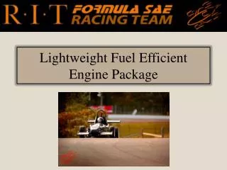
Lightweight Fuel Efficient Engine Package . Brittany Borella , Chris Jones, John Scanlon, Stanley Fofano , Taylor Hattori, and Evan See. Project Overview. Customer Needs. Engineering Specifications. Engine Model. Air/Fuel Ratio: 0.86 Lambda

E N D
Lightweight Fuel Efficient Engine Package Brittany Borella, Chris Jones, John Scanlon, Stanley Fofano, Taylor Hattori, and Evan See
Air/Fuel Ratio: 0.86 Lambda • Simplified tubular geometry used for initial induction and exhaust models • CRF250R valve flow scaled until WR450F data is measured • Wiebe combustion model parameters currently estimated until cylinder pressure data is obtained • Ignore effects of muffler • Surface roughness values estimated • Wall heat transfer properties estimated for steel exhaust sections • Intake and exhaust valve lift estimated from YZ400F until actual measurements can be made • Assume constant operating temperature and component temperatures—to be correlated with dyno data • Assume ambient conditions of 14.7 psia and 80°F Overall Assumptions
Finalized intake/throttle/restrictor geometry • Finalized injector placement(s) • Injector flow data • Intake/exhaust valve inflow and outflow loss coefficients • Intake/exhaust cam profiles • Base cam timing • General cranktrain dimensions • Surface area ratios for head and pistons • P-V Diagrams to validate Wiebe model assumptions • Various temperature measurements Required Parameters
Flow Testing of Cylinder Head Bore Tube Production Photo Courtesy of DUT Racing
Engine Characterization • Torque • P-V Diagrams • Brake Specific Fuel Consumption • Cooling System • Sensors • Cylinder Pressure • Crank angle • Thermocouples • Fuel Flow • Coolant Flow • Basic Engine Diagnostics • Wideband Lambda Engine Testing
FT-210 Series • Gems Sensors & Control • 0.026 - 0.65 gal/min • ± 3% Accuracy Fuel Flow Sensor
PCB Piezotronics • Transducer 112B10 • 422E In-Line Charge Converter Cylinder Pressure Sensor
AM4096 - 12 bit rotary • Measure Angular Position • Outputs • Incremental • Series SSI • Linear Voltage • Analogue Sinusoidal Magnetic Encoder
Load Simulation • Power Characterization • Fuel/Spark Mapping Dynamometer
Dynamometer Controller • Data Input Improvement • NI PCI-6024E • 200 kS/s • 12-Bit • 16-Analog-Input DAQ Data Acquisition
20 mm inlet diameter (19 mm for E85) creates choked flow conditions, limiting total mass airflow to engine • Required by competition rules • Keeps engine power at a safe level for competition • Design goal is to minimize loss coefficient through restrictor geometry to allow maximum airflow into engine • Supersonic Converging – Diverging Nozzle Geometry • Expand out diverging section to allow for proper shock development to minimize loss coefficient • Keep diffuser angle low enough to avoid potential flow separation • Keep overall length low to reduce viscous losses due to surface friction and boundary layer growth Intake Restrictor
2-Dimensional Axis-Symmetric analysis allows for fast solving time with refined mesh in areas of shock development Intake Restrictor
Air flows from throttle to engine intake port through intake manifold • Intake Plenum • Acts as air reservoir for engine to draw air from during intake stroke • Primary purpose is to damp out pressure pulses from intake stroke to create steady flow conditions at the restrictor • Intake Runner • Path through which engine pulls air from the plenum into the combustion chamber during intake stroke • Length decided by harmonic frequency at various engine operating speeds, can be used to create a resonant “tuning point” Intake Manifold
Transient Pressure Boundary Condition used to simulate pressure pulses within manifold from intake stroke • Piecewise-Linear Approximation used for initial analysis trouble-shooting • End analysis will use pressure trace measured during Dynamometer Testing Intake Manifold
Component Simulation • Shroud structure analyzed to ensure uniform airflow distribution across radiator face and verify proper mass airflow through radiator • Radiator modeled as a material resistance with heat addition and flow re-direction to properly simulate airflow through core Cooling System Airflow
Full Car Simulation to verify shroud is receiving adequate airflow • Simulation model still in progress, needs additional geometry and refinement Cooling System Airflow
Overflow Tank Surge Tank Cooling System Schematic Steam from Cylinder Head Thermostat Radiator Fan Engine Block Water Pump
Modify for bleed line to Surge Tank • Rule of thumb: 1.1 in2 radiator surface area needed per hp produced • Therefore need approx. 66 in2 • Radiator from YFZ450R Yamaha ATV • 7.5” H x 11.5” W x 7/8” D • Surface Area 86.25 in2 • Inlet and Outlet ¾” ID tubing to connect to water pump Radiator Inlet from Engine Outlet to Water Pump
Coolant naturally builds to approximately 16-18 psi • Normal production cars run 16-18 psi, high performance cars run 22-24 psi , and racing systems run 29-31 psi • Pressurizing the water allows for the water to reach a higher temperature before boiling (therefore vaporizing) • Part# T30R Radiator Cap 29-31 PSI Radiator Cap
Typically a 1 quart container • Need to modify the part of the Radiator that currently has the cap and overflow line to run a ¼”- 3/8” bleed line from radiator to top of surge tank • ½” – ¾” Refill line from bottom of surge tank to inlet of water pump • Benefits – de-aeration • 2% air in the system leads to an 8% decrease in cooling efficiency • 4% air in the system leads to a 38% decrease in cooling efficiency! 30 PSI Pressurized Radiator Cap Bleed line inlet from radiator and cylinder head Surge Tank Outlet to overflow tank Refill line back to water pump
Comes stock on engine • No internal bypass system. Thermostat will have to regulate continual water flow through engine • ¾” ID inlet and outlet tubing to connect to radiator Need to test flow rate once we have the cylinder head again Water Pump Flow Rate vs. RPM from R6 water pump
Placed at the outlet of the engine, a thermostat allows water to circulate through the block, but doesn’t allow this water to circulate through the radiator until it has reached proper operating temperature • This temperature (195°F) melts the “wax motor”, which forces the thermostat piston to open and allows the water to flow through. • If the engine’s temperature is lowered too much, the piston closes until it has reached proper operating temperature once again Thermostat • Stewart/Robert Shaw Thermostats – 302 • Augments bypass system • $14.95
Reviewed three sets of autocross runs with different drivers Cooling System Data
Verify radiator is receiving adequate airflow at low speeds • SPAL Axial Fan • 11” Dia. • 755.0 CFM • Based on predicted power require minimum 450 CFM • Based on airflow at speed available require minimum 500 CFM • Maximum 7” Dia. to fit radiator • Yamaha R6 Fan • 5.5” Dia. • Est. >500 CFM Fan • Q = required heat rejected into air