Download
1 / 29
410 likes | 1.05k Views
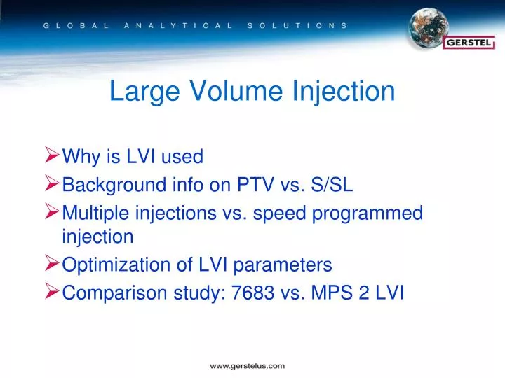
Large Volume Injection. Why is LVI used Background info on PTV vs. S/SL Multiple injections vs. speed programmed injection Optimization of LVI parameters Comparison study: 7683 vs. MPS 2 LVI. Large Volume Injection (LVI). Increase sensitivity Reduce or eliminate solvent extraction steps

E N D
Large Volume Injection Why is LVI used Background info on PTV vs. S/SL Multiple injections vs. speed programmed injection Optimization of LVI parameters Comparison study: 7683 vs. MPS 2 LVI
Large Volume Injection (LVI) Increase sensitivity Reduce or eliminate solvent extraction steps Improve detection limits
Typical S/S Injector Set temperature high enough to completely vaporize sample Flow depends on split ratio Injection port volume 980 ul Mode either split or splitless Fixed septum purge/vent flow
CIS Inlet Similar plumbing to S/S inlet Sample injected as liquid - volatilized as temperature is programmed No septum Volume 220 ul Multi mode S/SL, hot or cold, solvent vent, on-column GRAPHPACK ferrules
LVI: Speed-programmed Injection Basic rule: Injection speed = evaporation rate i.e. The injected liquid solvent has to leave the injector gaseous liquid, in gaseous, out
LVI Liner Considerations Liner volume ; for example, a CIS 4 liner: 220 l volume (max). Liner treatments or deactivation. Liner design- baffled liner for LVI (<15 l) glass wool packed liner for >15 L Tenax TA or PDMS foam for additional discrimination when BP difference is <150 oC Use Agilent Flow Calc to check vapor volumes under injection conditions
Large Volume Injection (LVI) Slow introduction of analyte into the injection port liner Solvent is vented while analytes of interest are trapped in the liner Optimum conditions for removing the solvent involves use of solvent-vent-stop flow (SVSF), possible with the CIS inlets. Using SVSF, the solvent is vented to atmosphere through a straight path and the column head pressure is reduced to ambient pressure.
Injection port liner • Injection volume 15 uL or less use an unpacked baffled liner • Injection volume more than 15 uL use glass wool or beads • LVI causes non-volatiles to build up in the liner, check frequently Injection port temperature • Best results are obtained when the BP difference between solvent and analyte is at least 150 ºC. • Set initial temperature to 30 ºC below the BP of the solvent LVI Optimization
Calculation of the Vaporization Rate Calculation of the vaporization rate can be performed using the LVI Calculator in the GERSTEL MAESTRO software. Additional solvents can be added to the solvent library.
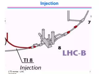
Large Volume Technique Programming the inlet pneumatics in ChemStation:STOPPED FLOW Gas flow for solventevaporation Venting time after injection Column pressure during the injection(Stopped Flow) At this time the split will open again.
Large Volume Technique Example of programming a CIS 4 in MAESTRO Software with 0.5 min solvent venting CIS Initial Time = Vent Time
LVI Optimization Procedure • Perform 1 uL splitless injection • Perform 1 uL SVSF injection • Dilute sample 10x and inject 10 uL • Dilute sample to target conc. and inject • Optimize to maintain peak shape
1. Perform 1 uL Splitless Injection • Determine mass of analyte needed on-column in final sample (e.g. 50 ng) • Prepare standard so 1 uL contains that mass of analyte (e.g. 50 ng/uL) • Inject 1 uL splitless to obtain reference area counts for analyte
2. Perform 1 uL SVSF Injection • Set inlet and injection conditions to suggested LVI starting conditions. • Start with a Vent Time of 0.1 min and a splitless transfer time of 1.0 min • Inject 1 uL std to obtain SVSF area counts for analyte. Area and precision should match splitless result.
3. Dilute Sample and Increase Injected Volume • Dilute sample 10x and inject 10 uL using SVSF • Inspect solvent peak • Inspect peak shape, recovery, reproducibility • Modify injection conditions to reduce solvent to 1 uL splitless level and improve peak shape, recovery, reproducibility. • Parameters to modify in this order: Vent time, PTV initial temp, Injection speed, vent flow, liner type
4. Dilute Sample and Increase Injected Volume • Dilute sample to target concentration inject icreased volume using SVSF • Inspect solvent peak • Inspect peak shape, recovery, reproducibility • Modify injection conditions to reduce solvent and improve peak shape, recovery, reproducibility.
5. Optimize LVI Parameters • Vent time: increase vent time to reduce solvent peak • PTV initial temp: reduce stepwise to solvent freezing point • Injection speed: reduce stepwise up to 3x • Vent flow: 50-300mL/min • Liner Type: • Baffled • Glass wool • Glass beads • Tenax TA • PDMS foam