Download
1 / 32
781 likes | 3.05k Views
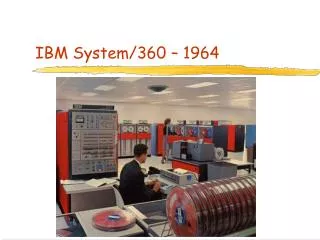
The IBM 360/370 Architecture. By: Yuxin Tao Emily Hwang July 25, 2001. History of IBM System/360/370. IBM System/360 was announced in April 1964. System/360 was the first line of processors with upward and downward compatibility.

E N D
The IBM 360/370 Architecture By: Yuxin Tao Emily Hwang July 25, 2001
History of IBM System/360/370 • IBM System/360 was announced in April 1964. • System/360 was the first line of processors with upward and downward compatibility. • System/360 was the first major product line designed for both business and scientific need.
History of IBM System/360/370 (Cont.) • IBM System/370 was announced in June 1970. • Addressing and virtual memory architectures are created and enhanced the performance of 370. • System/370 had an execution time 3 to 5 times faster than system/360 model 50 and 60.
Virtual Memory • Once given a virtual memory system, it was seen to be feasible with appropriate software to create virtual machines, to operate several of them in time-shared fashion, and in fact to provide each active terminal with a virtual machines of its own. • Virtual memory technology ensured increased efficiency in the use of memory.
Virtual Memory (Cont.) • System/370’s virtual memory of 16 megabytes was represented as an area in disk storage. During execution, “pages” of program content were moved on an as-needed basis from disk to memory, or vise versa, by the control program. • This meant that a disk-stored page could be brought to any available page-sized frame in physical memory. This meant that it was no longer necessary to define a separate memory area for each of the programs executed at the same time.
Virtual Memory (Cont.) • The virtual memory capability was announced in August 1972. It opted for a 24-bit virtual address. • Not only could the Virtual memory provided by translation ease the planning and preparation of software, but it could generalize the utility of programs.
Addressing • In System/370, a 24-bit virtual address is generated. The address is the the address of a byte but may actually refer to one or more bytes depending on the op code. • Three basic addressing modes are supported: immediate, register, and storage. • An immediate operand is a 1-byte value contained in some instructions.
Addressing (Cont.) • A register operand is contained in a general register or a floating-point register, depending on the instruction. • A storage operand is contained in virtual memory. Each storage-operand reference consists of a 12-bit displacement and a 4-bit register identifier that designates one of the general registers. If the register identifier is 0, it indicates that the register is component is not to be used.
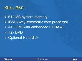
Components of System/370 • A System/370 model is composed of five different types of functional units: storage, a CPU, input/output channels, control units, and input/output devices. • The basic unit of addressable main storage in System/370 is the 8-bit byte, which can represent one character, two decimal digits, or eight binary bits. • Character information is conveniently represented as 8-bit units of information allowing 256 possible characters.
Components of System/370(Cont.) • System/370 uses the Extended Binary Coded Decimal Interchange Code( EBCDIC ). • Numeric data may be stored in any of four formats: zoned decimal, packed decimal, fixed-point binary, and floating-point binary. • The System/370 includes three formats for floating point binary data: short, long, and extended. • Local storage in System includes 16 general registers and 4 floating-point registers.
Registers in System/370 • Each general register has a capacity of a full word (32 bits ) and can be used for arithmetic and logical operations and in address arithmetic and addressing. • The general registers are numbered 0 through 15 and are identified by a 4-bit R field in a computer instruction. • The floating-point register is a double word ( 64 bits ) in length and can hold either a short, long, or extended precision floating-point number.
Operation Types • The System/370 principles of operations defines five broad classes of machine instructions: • General: fixed-point arithmetic instruction, logical instruction, general register shifting instruction, general register load & store instructions, compare instruction, branch instructions, conversion instructions. • Decimal: decimal instructions
Operation Types( Cont.) • Floating point: floating-point instructions • Privileged I/O: special-purpose control instructions, privileged I/O instructions • Privileged System Control: privileged system-control instructions
Type Example Format Description Examples of System/370 Operation Type Fixed-point arithmetic Logical General register shifting AH R1, D2 ( X2, B2) XI D1(R1), I2 SLDL R1, D2 (R2) RX SI RS Add second operand to first. Second operand is 16 bits; the first operand and result are 32 bits The XOR of I2 and the byte at D1(R1) are stored at D1(R1) Shift left double logical. The 64-bit double register at R1 is shifted left the number of bits specified by the rightmost 6 bits of D2. R2 and remainder of D2 are ignored.
Examples of System/370 Operation Type(Cont.) Type Example Format Description General register load & store Data Moving, conversion & translation Decimal LCR R1, R2 MVN D1(L, R1), D2 ( R2) AP D1(L1, R1), D2 ( L2, R2 ) RR SS SS The 2’s complement of the second operand is placed in the first The rightmost 4 bits of the L bytes beginning at D2(R2) are moved to the rightmost 4 bits of the corresponding bytes at D1(R1). The leftmost 4 bits are unchanged. The second operand is added to the first. Both are in packed decimal format of the lengths indicated.
Examples of System/370 Operation Type(Cont.) Type Example Format Description Floating-point Compare Special-purpose control Privileged I/O AD R1, D2 ( X2, R2 ) CR R1, R2 SVC I SIO D2( R2 ) RX RR RR S Add second operand to first. Normalize result. Compare two operands and set condition code ( 0; equal; 1: ( R1 < R2 ); 2: ( R1 > R2 ). Causes an interrupt, with the I field providing part of the interruption code. Start I/O. Bits 16-31, D2(R2), identify the channel, subchannel, and device
IBM/370 Instruction Format • System/370 has six different formats: RR, RX, RS, SI, SS, and S type instructions. • The formats differ in the addressing characteristics – whether operands are in registers, in the instruction itself, or in main storage addressed by base and displacement or by base, index, and displacement. • Because of the variation in space required, some instructions occupy two bytes of storage, others are four bytes long, and still others are six bytes long.
IBM/370 Instruction Format (Cont.) • In all System/370 instructions the first one or two bytes are the operation code, which indicates the length of the instruction and the type of operation to be perform. • Although the 370 instruction set is rich, the formats are straightforward and make reasonably efficient use of instruction length. • Both register and memory references are used, in various combinations, and two op code lengths are employed.
Bits 0 7 8 11 12 15 Six Instruction Format: I • RR Type Instructions: Both operands of each of these instructions are in registers. The instruction is therefore two bytes long. An example of RR-type instruction coded in hexadecimal as 1837. The op-code is 18, means load from a register. The operand addresses are 3 and 7; execution of the instruction causes the contents of register 7 to be loaded into register 3. Content of register 3 has been replaced, but register 7’s content remains unchanged.
Six Instruction Format: II • RX Type Instructions: The first operand is a register and the second operand is located in main storage. Its address is specified by a base B2, index X2 and a displacement given in bits 20-31 of the instruction. Bits 0 7 8 11 12 15 16 19 20 31 An example of RX-type instruction coded in hexadecimal as 5B35C024. The op-code is 5B, mean subtract. The first operand is register in register 3, the field X2 is 5, the field B2 is C, the displacement is 024. So the second operand is X2 + B2 + D2 = 007478, means the effective address is 07478. This instruction will be executed as: the contents of location 007478 will be subtracted from the contents of register 3. The result will be left in register 3.
Six Instruction Format: III • RS Type Instructions: The first operand is a register R1 and the second operand is located in main storage, with address specified by base B2, and a displacement D2. The third operand is a register operand R3. Bits 0 7 8 11 12 15 16 19 20 31 An example of RS-type instruction coded in hexadecimal as 9868C024. The op-code is 98, mean load multiple. The first operand is register in register 6, the field B2 is C, the field D2 is 024, if register C contains 00007404, then the second operand address is : 00007404+024 = 007428. The third operand is register 8. The execution result will be: registers from 6 to 8 will be loaded from consecutive locations of main storage, starting with location 007428.
Six Instruction Format: IV • SI Type Instructions: The first operand is in main storage, with address specified by base B1 and displacement D1. The second operand is the eight-bit immediate operand I2. Bits 0 7 8 15 16 19 20 31 An example of SI- type instruction coded in hexadecimal as 92F3C231. The op-code is 92, mean move immediate. The first operand is register C and displacement is 231. If C contains 00007404, the operand address is 00007404+231 = 007635. The execution of instruction is stored the data F3 at location 00007635 of the main storage.
Six Instruction Format: V • SS Type Instructions: Both operands are in main storage, the first operand is S1+D1, the second operand is B2+D2, the value of L plus 1 indicates the operand length. Bits 0 7 8 15 16 19 20 31 32 35 36 47 An example of SS-type instruction coded in hexadecimal as D202C106C735. The op-code is D2 means move character. The first operand address is register C content+106, the second operand address is C content+ 735. The execution of this instruction, the three bytes( L value + 1 ) beginning at location C+106 are moved to three storage locations beginning at C+735.
Six Instruction Format: VI • S Type Instructions: This is the only type in which the op-code is two bytes long. The single operand is determined by base B2 and displacement D2 in the usual way. All S type instruction are connected with advanced functions and almost all of the advanced functions are reserved for use in supervisor state. Bits 0 15 16 19 20 31
Summary of Instruction Format • The variety of instruction types is designed to give flexibility in length and location of operands. • Both register and memory references are used, in various combinations, and two op code length either 1 byte or 2 bytes are employed. • The formats are straightforward and make reasonably efficient use of instruction length. Three different instruction lengths – 2 bytes, 4 bytes, or 6 bytes are used.
A Register Another Register RR type RS type RX type Main Storage Location SS type Another main Storage location SI type Byte in Instruction Operand Configuration of Instructions( Summary )
MIPS Instruction Format • R-format • I-format • J-format Bits 31 26 25 21 20 12 15 11 10 6 5 0 Bits 31 26 25 21 20 16 15 0 Bits 31 26 25 0
Problems in System/360/370 • System/370 stored its operating instructions in the semi-conductor memory which meant that whenever the computer was shut off, the memory was erased. • In order to restart the computer, the control program had to be reloaded into memory. • The solution to it was the invention of the 8-inch floppy disk that was used to store and ship micro-code.
Success of System/360/370 • System/360 had a overall circuit failure rate about 0.001 percent per thousand hours. • System/360 was so pioneer that, at the time, it’s architecture and engineers shattered the data processing industry’s conventional distinction between computers for business and computers for science
Success of System/360/370 (Cont.) • System/360 served the needs of customers by reducing their data processing costs and supporting the undertaking of additional application. • In 1989, a quarter century after the system/360 was introduced, computers based on the 360-370 architecture accounted for more than half of the estimated $260 billion value of these large computer systems installed worldwide.
Success of System/360/370 (cont.) • The most significant technical achievement of the 360/370 lay in the attainment of product-line compatibility. • So attractive and successful were the system concepts that others chose to develop 360/370 compatible lines as RCA’s Spectra 70 series and the Soviet Unions Ryad computers.
References • William Stallings, Computer Organization and Architecture – Principles of Structure And Function. Macmillan Publishing Company, New York, NY., 1987 • George W. Struble, Assembler Language Programming: the IBM System/360 and 370. Addison-Wesley Publishing Company, Inc., 1975 • Pugh, Johnson, Palmer., IBM’s 360 and Early 370 System. The MIT Press. Cambridge, MA., 1991. • Mano, M. Morris,. Computer System Architecture. Prentice Hall. Englewood Cliffs, NY., 1993