Download
1 / 58
620 likes | 936 Views
Cellular Systems-- Cellular Concepts. The cellular concept was a major breakthrough in solving the problem of spectral congestion and user capacity. It offered very high capacity in a limited spectrum allocation without any major technological changes.

E N D
Cellular Systems--Cellular Concepts • The cellular concept was a major breakthrough in solving the problem of spectral congestion and user capacity. It offered very high capacity in a limited spectrum allocation without any major technological changes. • The cellular concept has the following system level ideas • Replacing a single, high power transmitter with many low power transmitters, each providing coverage to only a small area. • Neighboring cells are assigned different groups of channels in order to minimize interference. • The same set of channels is then reused at different geographical locations.
Cellular Concepts • When designing a cellular mobile communication system, it is important to provide good coverage and services in a high user-density area. • Reuse can be done once the total interference from all users in the cells using the same frequency (co-channel cell) for transmission suffers from sufficient attenuation. Factors need to be considered include: • Geographical separation (path loss) • Shadowing effect
Cell Footprint • The actual radio coverage of a cell is known as the cell footprint. • Irregular cell structure and irregular placing of the transmitter may be acceptable in the initial system design. However as traffic grows, where new cells and channels need to be added, it may lead to inability to reuse frequencies because of co-channel interference. • For systematic cell planning, a regular shape is assumed for the footprint.
Cell Footprint • Coverage contour should be circular. However it is impractical because it provides ambiguous areas with either multiple or no coverage. • Due to economic reasons, the hexagon has been chosen due to its maximum area coverage. • Hence, a conventional cellular layout is often defined by a uniform grid of regular hexagons.
Frequency reuse • A cellular system which has a total of S duplex channels. • S channels are divided among N cells, with each cell uses unique and disjoint channels. • If each cell is allocated a group of k channels, then S = k N .
Terminology • Cluster size : The N cells which collectively use the complete set of available frequency is called the cluster size. • Co-channel cell : The set of cells using the same set of frequencies as the target cell. • Interference tier : A set of co-channel cells at the same distance from the reference cell is called an interference tier. The set of closest co-channel cells is call the first tier. There is always 6 co-channel cells in the first tier.
Co-ordinates for hexagonal cellular geometry • With these co-ordinates, an array of cells can be laid out so that the center of every cell falls on a point specified by a pair of integer co-ordinates.
Designing a cellular system • N=19 • (i=3, j=2)
Designing a cellular system • The cluster size must satisfy: N = i2 + ij + j2 where i, j are non-negative integers.
Designing a cellular system • Can also verify that where Q is the co-channel reuse ratio
Handover / Handoff • Occurs as a mobile moves into a different cell during an existing call, or when going from one cellular system into another. • It must be user transparent, successful and not too frequent. • Not only involves identifying a new BS, but also requires that the voice and control signals be allocated to channels associated with the new BS.
Handover / Handoff • Once a particular signal level Pmin is specified as the minimum usable signal for acceptable voice quality at the BS receiver, a slightly stronger signal level PHO is used as a threshold at which a handover is made.
Handover / Handoff • =handoff threshold - Minimum acceptable signal to maintain the call • too small: • Insufficient time to complete handoff before call is lost • More call losses • too large: • Too many handoffs • Burden for MSC
Dwell Time • The time over which a user remains within one cell is called the dwell time. • The statistics of the dwell time are important for the practical design of handover algorithms. • The statistics of the dwell time vary greatly, depending on the speed of the user and the type of radio coverage.
Handover indicator • Each BS constantly monitors the signal strengths of all of its reverse voice channels to determine the relative location of each mobile user with respect to the BS. This information is forwarded to the MSC who makes decisions regarding handover. • Mobile assisted handover (MAHO) : The mobile station measures the received power from surrounding BSs and continually reports the results of these measurements to the serving BS.
Prioritizing Handover • Dropped call is considered a more serious event than call blocking. Channel assignment schemes therefore must give priority to handover requests. • A fraction of the total available channels in a cell is reserved only for handover requests. However, this reduces the total carried traffic. Dynamic allocation can improve this. • Queuing of handover requests is another method to decrease the probability of forced termination of a call due to a lack of available channel. The time span over which a handover is usually required leaves room for queuing handover request.
Practical handover • High speed users and low speed users have vastly different dwell times which might cause a high number of handover requests for high speed users. This will result in interference and traffic management problem.
Practical handover • The Umbrella Cell approach will help to solve this problems. High speed users are serviced by large (macro) cells, while low speed users are handled by small (micro) cells.
Practical handover • A hard handover does “break before make”, ie. The old channel connection is broken before the new allocated channel connection is setup. This obviously can cause call dropping. • In soft handover, we do “make before break”, ie. The new channel connection is established before the old channel connection is released. This is realized in CDMA where also BS diversity is used to improve boundary condition.
Interference and System Capacity • In a given coverage area, there are several cells that use the same set of frequencies. These cells are called co-channel cells. The interference between signals from these cells is called co-channel interference. • If all cells are approximately of the same size and the path loss exponent is the same throughout the coverage area, the transmit power of each BS is almost equal. We can show that worse case signal to co-channel interference is independent of the transmitted power. It becomes a function of the cell radius R, and the distance to the nearest co-channel cell D’.
Interference and System Capacity • Received power at a distance d from the transmitting antenna is approximated by • Useful signal at the cell boundary is the weakest, given by Pr (R). Interference signal from the co-channel cell is given to be Pr (D′) .
Interference and System Capacity • D’ is normally approximated by the base station separation between the two cells D, unless when accuracy is needed. Hence
Interference and System Capacity • For the forward link, a very general case, where Diis the distance of the ith interfering cell from the mobile, i0 is the total number of co-channel cells exist.
Interference and System Capacity • If only first tier co-channel cells are considered, then i0 = 6. Unless otherwise stated, normally assuming Di≈ D for all i.
Outage probability • The probability that a mobile station does not receive a usable signal. • For GSM, this is 12 dB and for AMPS, this is 18 dB. If there is 6 co-channel cells, then • Exercise : please verify this • For n=4, a minimum cluster size of N=7 is needed to meet the SIR requirements for AMPS. • For n=4, a minimum cluster size of N=4 is required to meet the SIR requirements for GSM
Outage probability • Approximation in distance has been made on the 2nd tier onwards.
Outage probability • More accurate SIR can be obtained by computing the actual distance. • Our computation of outage only based on path loss. For more accurate modeling, shadowing and fast fading need to be taken into consideration. This will not be covered in this course.
Coverage Problems • Revision: • Recall that the mean measured value, • Measurement shows that at any value of d, the path loss PL(d) at a particular location is random and distributed log-normally (normal in dB) about this mean value. Pr (d)dB = Pr (d)dB + Xσ where Xσ is a zero-mean Gaussian distributed random variable (in dB) with standard deviation σ(in dB).
Boundary coverage • There will be a proportion of locations at distance R (cell radius) where a terminal would experience a received signal above a threshold γ. (γ is usually the receiver sensitivity) • where Q(x) is the standard normal distribution.
Cell coverage • Proportion of locations within the area defined by the cell radius R, receiving a signal above the threshold γ.
Cell coverage • Solution can be found using the graph provided. (n : path loss exponent)
Cell coverage • Example: if n=4, σ=8 dB, and if the boundary is to have 75% coverage (75% of the time the signal is to exceed the threshold at the boundary), then the area coverage is equal to 94%. • If n=2, σ=8 dB, and if the boundary is to have 75% coverage, then the area coverage is equal to 91%. • An operator needs to meet certain coverage criteria. This is typically the “90% rule” – 90% of a given geographical area must be covered for 90% of the time.
Cell coverage • The mean signal level at any distance is determined by path loss and the variance is determined by the resulting fading distribution (log-normal shadowing, Rayleigh fading, Nakagami-m, etc). In this course, we will deal with log-normal shadowing only. • The proportion of locations covered at a given distance (cell boundary, for example) from BS can be found directly from the resultant signal pdf/cdf. • The proportion of locations covered within a circular region defined by a radius R (the cell area, for example) can be found by integrating the resultant cdf over the cell area.
Cell coverage --Cellular Traffic • The basic consideration in the design of a cellular system is the sizing of the system. Sizing has two components to be considered. • Coverage area • Traffic handling capability • After the system is sized, channels are assigned to cells using the assignment schemes mentioned before.
Cell coverage --Terminology in traffic theory • Trunking : exploits the statistical characteristics of the users calling behaviour. Any efficient communication system relies on trunking to accommodate a large number of users with a limited number of channels. • Grade of service (GoS) : A user is allocated a channel on a per call basis. GoS is a measure of the ability of a user to access a trunked system during the busiest hour. It is typically given as the likelihood that a call is blocked (also known as blocking probability mentioned before). • Trunking theory : is used to determine the number of channels required to service a certain offered traffic at a specific GoS. • Call holding time (H) : the average duration of a call. • Request rate (λ) : average number of call requests perunit time.
Cell coverage --Traffic flow or intensity A • Measured in Erlang, which is defined as the call minute per minute. • Total offered traffic for such a system is given as A = λ ⋅H • Exercise : There are 3000 calls per hour in a cell, each lasting an average of 1.76 min. Offered traffic A = (3000/60)(1.76) = 88 Erlangs
Cell coverage • If the offered traffic exceeds the maximum possible carried traffic, blocking occurs. There are two different strategies to be used. • Blocked calls cleared • Blocked calls delayed • Trunking efficiency : is defined as the carried traffic intensity in Erlangs per channel, which is a value between zero and one. It is a function of the number of channels per cell and the specific GoS parameters. • Call arrival process: it is widely accepted that calls have a Poisson arrival.
Channel Assignment Strategies • Channel allocation schemes can affect the performance of the system. • Fixed Channel Allocation (FCA) : • Channels are divided in sets. • A set of channels is permanently allocated to each cell in the network. Same set of channels must be assigned to cells separated by a certain distance to reduce co-channel interference. • Any call attempt within the cell can only be served by the unused channels in that particular cell. The service is blocked if all channels have used up.
Channel Assignment Strategies (FCA) • Most easiest to implement but least flexibility. • An modification to this is ‘borrowing scheme’. Cell (acceptor cell) that has used all its nominal channels can borrow free channels from its neighboring cell (donor cell) to accommodate new calls. • Borrowing can be done in a few ways: borrowing from the adjacent cell which has largest number of free channels, select the first free channel found, etc. • To be available for borrowing, the channel must not interfere with existing calls. The borrowed channel should be returned once the channel becomes free.
Channel Assignment Strategies (DCA) • Dynamic Channel Allocation (DCA) : • Voice channels are not allocated to any cell permanently. All channels are kept in a central pool and are assigned dynamically to new calls as they arrive in the system. • Each time a call request is made, the serving BS requests a channel from the MSC. It then allocates a channel to the requested cell following an algorithm that takes into acount the likelihood of future blocking within the cell, the reuse distance of the channel and other cost functions ⇒ increase in complexity • Centralized DCA scheme involves a single controller selecting a channel for each cell. Distributed DCA scheme involves a number of controllers scattered across the network. • For a new call, a free channel from central pool is selected based on either the co-channel distance, signal strength or signal to noise interference ratio.
Channel Assignment Strategies • Flexible channel assignment • Divide the total number of channels into two groups, one of which is used for fixed allocation to the cells, while the other is kept as a central poor to be shared by all users. • Mix the advantages the FCA and DCA, available schemes are scheduled and predictive. • Channels need to be assigned to users to accommodate • new calls • handovers with the objective of increasing capacity and minimizing probability of a blocked call.
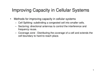
System Expansion Techniques • As demand for wireless services increases, the number of channels assigned to a cell eventually becomes insufficient to support the required number of users. More channels must therefore be made available per unit area. • This can be accomplished by dividing each initial cell area into a number of smaller cells, a technique known as cell-splitting. • It can also be accomplished by having more channels per cell, i.e. by having a smaller reuse factor. However, to have a smaller reuse factor, the co-channel interference must be reduced. This can be done by using antenna sectorization.
System Expansion Techniques--Cell splitting • Cell splitting increases the number of BSs in order to increase capacity. There will be a corresponding reduction in antenna height and transmitter power. • Cell splitting accommodates a modular growth capability. This in turn leads to capacity increase essentially via a system re-scaling of the cellular geometry without any changes in frequency planning. • Small cells lead to more cells/area which in turn leads to increased traffic capacity.
System Expansion Techniques--Cell splitting • For new cells to be smaller in size, the transmit power must be reduced. If n=4, then with a reduction of cell radius by a factor of 2, the transmit power should be reduced by a factor of 24 (why?) • In theory, cell splitting could be repeated indefinitely. • In practice it is limited • By the cost of base stations • Handover (fast and low speed traffic) • Not all cells are split at the same time : practical problems of BS sites, such as co-channel interference exist • Innovative channel assignment schemes must be developed to address this problem for practical systems.