Download
1 / 21
210 likes | 564 Views
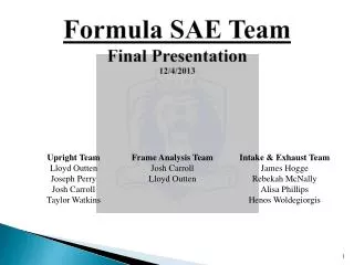
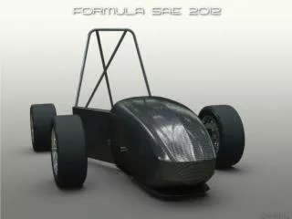
Formula SAE Team Midterm Presentation 10/30/2013. Front Upright Team Lloyd Outten Joseph Perry. Rear Upright Team Josh Carroll Taylor Watkins. Intake & Exhaust Team James Hogge Rebekah McNally Alisa Phillips Henos Woldegiorgis. Introduction to Formula SAE.

E N D
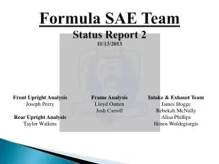
Formula SAE TeamMidterm Presentation10/30/2013 • Front Upright Team • Lloyd Outten • Joseph Perry • Rear Upright Team • Josh Carroll • Taylor Watkins • Intake & Exhaust Team • James Hogge • Rebekah McNally • Alisa Phillips • Henos Woldegiorgis
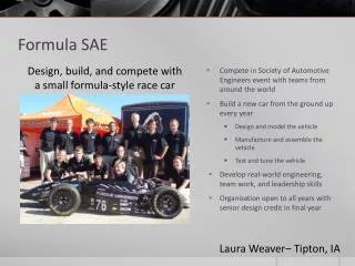
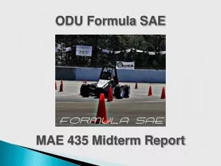
Introduction to Formula SAE • Design Competition for Collegiate students • Represent ODU’s Engineering Department • 8 part competition (8 Events)
Uprights [Car 106 Front Upright] [Car 106 Rear Upright]
Front Upright Design Process Below ¼” added to the rear of the upright at top and bottom to support brake bracket Flaws: Brake Bracket Needed to be ¼” more toward the outside to properly line up the caliper with the brake rotor Excess Material on Steering Bracket Flaws: Steering Bracket Not Double Shear Stepped Brake Bracket Eyesore and Possible cause for Failure [Model that was 3D Printed]
Rapid Prototyping Corrections Made After Rapid Prototyping: -Threaded Hole Size For Brake Bracket -Height and Depth of Lower A-Arm Recess -Material Added Between Steering Bracket Tabs -Bolted Brake Bracket Advantages of Using Rapid Prototyping -Fast and Efficient Way of Reinforcing Design Dimensions -Relatively Cheap to Produce
Front Upright Assembly Upper A-Arm Bracket [Left removable for camber adjustments] Brake Bracket Upper A-Arm Connection Brake Caliper Connection Spec Sheet Material: 6061 Aluminum Total Assembly Weight: 2.28 lb. Total Assembly Volume: 23.85 in3 Weight by Part Main Upright 1.69 lb. Brake Bracket 0.44 lb. Upper A-Arm Bracket 0.12 lb. Spindle Connection Steering Connection Lower A-Arm Connection Main Upright
Rear Upright Design Process • Initial Design • Model of current upright • Working design needing optimization • Reduce weight while maintaining strength • 2.51 lbs • Possible Changes • Remove Webbing • Reduce Thickness • Optimize Material • Al 6061 Alloy decided upon
Rear Upright Design Process • First Design • Removal of webbing • Slightly lighter than initial design • 2.46 lbs • Preliminary stress analysis reveal high factor of safety throughout part
Rear Upright Design Process • Second Design • Reduced thickness of part by 0.25” • Bearing thickness remains the same • 2.32 lbs • Preliminary stress analysis revealed high factor of safety throughout part
Rear Upright Design Process • Final Design • Combination of design one and two • Thickness reduced to 0.75” • Webbing removed • Lightest of all designs • 1.64 lbs • Fillet added between feet and bracing bar to reduce stress concentration • Resized after prototype test fit
What Comes Next Expected Cost Report Total Price (without shipping and taxes, including a 10% discount) = $538.69
Intake & Exhaust • Problem Statement: • To design and build an intake that delivers maximum performance possible for our engine. • Accomplishments this year: • Researched different intake styles and chose the most efficient style • Created and revised design in Solidworks • Ran design through SolidWork’s flow analysis program • Revised our design in accordance to flow results (Still in progress) • Researched material costs
Research: Intake • Research determined that a spherical collector upright intake was the most efficient design • (1). The taper of the cone collector should be between 3-7 degrees • (2). Optimal runner length of 250-325mm • (3). 20 mm FSAE mandated restrictor (2) (3) (1)
Research: Exhaust • Typical stock exhaust uses small diameter crush bent pipe or mandrel bent pipe. • Crush bents are easier and cheaper to make however reduce the flow by 50%. • To produce the most power exhaust should have minimal restriction on the exact flow. • Components: 4 headers and silencer canister (muffler)
Solidworks: Intake Runners • Preliminary design • Goal of runners: Achieve maximum and even flow to all 4 cylinders • Revised (Final) Design
Solidworks: Intake Collector & Restrictor • Collector Version 1 (3 degree taper) • Restrictor Version 1 (for 3 degree collector) • Collector Version 2 (5 degree taper) • Restrictor Version 2 (for 5 degree collector)
Solidworks File: Final Assembly • Full Assembly • (3 degree collector) • Full Assembly • (5 degree collector)
Intake con’t • Analysis • Initial Testing using SolidworksFloXpress • Tests one intake runner at a time • Future testing with time dependent modeling across all four cylinders required for final analysis
Cost Report Total Estimated Cost $60
What’s Next? • Continue Flow Analysis • Ordering materials • Fabrication • Flowbench testing with fabricated intake to verify analysis results • Design of the exhaust once more components of the frame are assembled