Download
1 / 38
390 likes | 581 Views
Summary of CERN/GSI Meeting on RF Manipulations and LLRF in Hadron Synchrotrons , March 20-21 2014. Facility for Antiproton and Ion Research. SIS 100/300. SIS 18. UNILAC. Radioactive Ion Production Target. Existing facility: provides ion-beam source and injector for FAIR. HESR. Super

E N D
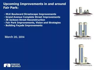
Summary of CERN/GSI Meeting on RF Manipulations and LLRF in Hadron Synchrotrons, March 20-21 2014
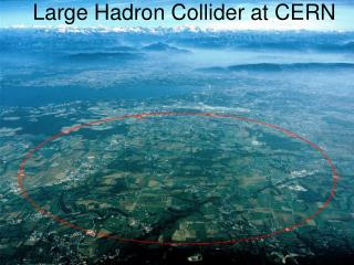
Facility for Antiproton and Ion Research SIS 100/300 SIS 18 UNILAC Radioactive Ion Production Target Existing facility: provides ion-beam source and injector for FAIR HESR Super FRS Anti-Proton Production Target CR 100 m FLAIR RESR NESR New future facility: provides ion and anti-matter beams of highest-intensity and up to high energies
Overview on the LLRF System Architecture for FAIR Harald Klingbeil
Control Aspects, LLRF Requirements • CW systems (e.g. accelerating systems) vs. pulsed systems (e.g. bunch compressor) • Cavities with "high" Q factor (e.g. accelerating systems, Q=5...10) vs. broadband cavities (e.g. barrier bucket, Q<1) → different response times • Fundamental RF frequencies: 300 kHz...5.4 MHz (exception: NESR high harmonics, CRYRING 10 kHz), partly with higher harmonics, fast ramping • Mutual synchronization of cavities required, also multi-harmonic (requirement ±3°, note: 1° phase deviation @ 5.4 MHz ↔ about 500 ps) • Mutual synchronization of synchrotrons (e.g. for bunch-to-bucket transfers) • Longitudinal beam stabilization (beam phase control, longitudinal feedback), especially for high beam intensities • Complex RF manipulations (barrier bucket, dual harmonic acceleration, bunch merging, etc.)
Bunch Merging Experiment 30./31.03.2012 This result that was obtained during the beam experiment. It is obvious that the bunches were merged in two steps as desired. Waterfall plot of the beam phase monitor signal for measurement
Experience & planning with digital low-level RF systems in small synchrotrons at CERN • Fully digital control • Modular: motherboard + different types of daughtercards • Several motherboards collaborate in real-time to implement DLLRF → low-latency digital links between boards. • Sweeping of tagged clock can be transmitted over optical fibres • Digital + analogue RF trains available. Also MDDS RF train at high h. • Extensive use of DSP (floating point) + FPGA (parallel) processing power. • FPGA: (mostly so far) infrastructure, to be setup but not modified • DSP: customisation of the processing to board function & machine • Remote FPGA/DSP configuration available Maria Elena Angoletta
Timings (now: firmware event triggered by counter) • Reference functions (directly digital). • Digital diagnostics (not black box!) • Digital signals from LLRF & digitized signals from other systems can be displayed in the same virtual scope. • Clock: loops sampling (constant, ~10 µs now) or RF (~fREV). • Digital LLRF overview in: • LEIR • PSB • MedAustron • ELENA • AD • Ion-therapy and research centre in Wiener-Neustadt (Austria) • Proton & Carbon ion therapy, clinical + non-clinical research • Synchrotron currently under commissioning (protons) • Treatment of first patient expected in late 2015.
MedAustron: LLRF layout Current status: cavity servoloop closed & operational. Beam in the synchrotron within days. Being commissioned now.
Longitudinal dynamics in the future FAIR SIS-100: transition crossing Original Proton Scenario in SIS-100 Do not cross transition SandraAumon
Crossing transition means…… Stable phaseshift @Transition Longitudinal dynamics @ Transition
Crossing transition energy in SIS-100 Constraint h in transition crossing chosen with bucket consideration
Phase and Amplitude Calibration of LLRF Components UtaHartel
Amplitude+phase calibration curve Counter phase measurements to try to minimize the sum voltage of the two cavities Result with CEL
A hardware family using VME VXS and FMC mezzanines for RF Low-level RF and Diagnostics applications in CERN's synchrotrons Digital LLRF Principle • Notes: • DDS = Digital Direct Synthesizer • DDC = Digital Down Converter John Molendijk
FMC Modules High Pin Count FMCs Developed ADC 16 bit 125 MS/s (DDC) • DAC 16 bit 250 MS/s (SDDS) • DDS (can be used as Master Direct Digital Synthesis) FPGA • Main FPGA manages the communication with: VXS, FMC_FPGA, VME64x, DSP. Main FPGA DSP FMC FPGA Notes: DDC = Digital Down Converter SDDS = Slave Digital Direct Synthesizer DSP= Digital Signal Processing FMCs
A New Frequency Program in the CERN Proton Synchrotron • B-field and revolution frequency information needed for various subsystems • Especially important as reference for RF beam control • Transmission protocol to be changed with renovation of B-train system • PS chosen for first White Rabbit implementation • Generate the revolution frequency, frev based on the following parameters: • B = Magnetic field strength of dipole magnets • Particle type (charge Ze, mass m) Magnus Sundal
White Rabbit Switch (WRS) • 18 ports, Gb/s, VLAN, HP MAC-address register, deterministic low-latency, transparent • Old system: • Instant distribution of Bdot (rate of change of B-field) • 10 µT resolution • New flexible frequency program for the PS developed for protons and ions: • Distribution of B, Bdot, G & S via White Rabbit • 50 nT resolution • Data rate of 250 kframes/s Key pointofWRS: • Ethernet based time synchronous network • Sub-ns accuracy/precision for synchronization • Deterministic low-latency data transfer • Existing hardware implementation • «Backwards compatible» with standard Ethernet • Successful validation of • B-field distribution via White Rabbit
The Collector Ring Debuncher Ulrich Laier
Collector Ring Debuncher System Overview CR DB LLRF requirements
Digital Generation of Radio Frequency References for the FAIR Acceleration Complex BuTiS= Bunch Phase Timing System is the dedicated time synchronization system for the FAIR project -> Fixed frequency transmission (not sweeping clocks). BuTiSgreenline Test installation BuTiS System=> synchronize the RF signal generated at different location connected with the White Rabbit (CERN Control and Timing Network ) B.Zipfel
Existingbunch-to-buckettransferschemes • Booster – PS and LEIR – PS • PS – SPS • SPS – LHC • Applications Thibault Ferrand Future applications • FAIR
Signal synchronisation • Re-synchronisation: one machine should synchronise on the second one or both machines must synchronise on an external clock. In both case the reference signal must be re-synchronised. • The different extraction, injection and instrumentation pulses are timed, taking into account the different hardware delays (kickers, pick-ups…) PS – SPS :
Implementation and control of RF manipulations in the PS • Recent LHC-type beams require more evolved RF manipulations • Sequences of: • Bunch splitting and merging • Batch compression and expansion • Buckets different during process Bucket number control • during both transfers PSB to PS • Bunches from PSB must be placed into the correct buckets • Batch compression works only for even number of bunches 1 turn Heiko Damerau
Reduce number of control parameters involved simplify operational maintainability • All cavities of group tuned to same frequency • Consequences of fixed tuning groups • Common harmonic number function per group • Common relative phase function per group • Voltage program group-to-cavity mapping Mapping from groups to cavities • voltageprograms • gap relay timings New hardware to generate digital voltage program data for each cavity • Flexible control matrix in software • Programming complexity reduced to the requirement of each beam • LHC-type beams: typically 10+2 functions and 4 timings • Single bunch low-intensity beams: 4+2 functions and no timing
Phase and radial loops closed and act on all RF harmonics simultaneously Pure h= 21 hPL Spectral component of beam (WCM) along RF manipulation 20/21 9/20 Digital local oscillator is programmable to any sequence of the harmonic number hPL Pure h= 9 hPL = 9/20 20/21 • For hRF = 9 10 20 21 phase loop at hPL = 9 20 21 sufficient • Bunches must be displaced symmetrically for averaged phase loop • Ekin = 1.4 GeV • Azimuthal position of 1st bunch ambiguous after RF manipulations: bucket/bunch number one? Bunch numbering convention PS-SPS • Convention: 1stbunch at fixed time position with respect to frev ,SPS frev marker from SPS Beam signal from wall current monitor • to switch between beams with different RF manipulations • to debug beam transfer between PS and SPS
Settings Generation for the RF Systems in FAIR Control System Representation of RF Systems & Settings Generation for FAIR David Ondreka
SIS 100 : generic prototype of RF manipulation Merging from h=10 to h=5
Status of the Longitudinal Feedback Developmentfor FAIR SIS 100 SIS 18 KerstinGroß
Simulations for SIS 18 machine experiment with beam this summer (@ fixed frequency with 2 bunches)
Final Amplifier, 10 MHz Cavity, Fast Wideband FB PS 10 MHz cavity feedback overview Gap Return - Fast wide-band feedback around amplifier (internal) Gain limited by delay - 1-turn delay feedback High gain at n frev - Slow voltage control loop (AVC) Gain control at fRF Drive DAC 1TFB ADC DAC AVC hn h200 Vprog Damien Perrelet H
Design choices and constraints • Old 1-turn feedback fully realized in hardware ECL logic little flexibility • Increase resolution of signal processing from 10 to 14 bits • Suppress multiple clocks and avoid double sampling at 4 fRF and 80 frev • Remove phase locked loopscuring associated unlocking issues due to sweeping • Problem for harmonics h=7 and 21 (LHC); remove need to start from h=8 (limitation in old system) • Improve delay compensation by dedicated parameters for each RF harmonic • Include a digital AVC in the firmware to replace the old analog hardware • Use a unique and increased sweeping clock for the sampling and the processing, integer multiple of the revolution frequency → hs=200 • Digital FPGA-based design: • → Improve flexibility, reliability, stability, reproducibility, drifts, … • Low latency components and firmware needed for the 1 turn-feedback • The system must follow the harmonic number provided by the control • Demodulation of multiple harmonics with a single clock → non-IQ • Variable automatic delay compensation during the cycle Why replace the existing feedbacks?
New 1-turn feedback board is ready and meets expectations • The two loops implemented 100% digital in the FPGA with more resolution • Good results without and with beam before LS1 • => Commissioning of the new system on the 11 cavities for the restart in 2014 • => Final adjustments and eventual modifications during setting-up • FPGA flexibility allows future new features like : • => generation of RF multi-harmonics onboard, RF cavity phase loop, cavity • phase compensation, studies to use higher sampling clock hs=256, .. Summary Electronic board EDA-02175-V2
Coupled-bunch feedback simulations and measurements in the Proton Synchrotron • In measurements done in 2013 before LS1 coupled-bunch feedback and the spare cavity have been used to excite and damp coupled-bunch oscillation. h=21 & 21 bunches h=21 & 18 bunches • Demonstrated existing already feedback with detection and excitation at different harmonics Letizia Ventura
Frequency domain longitudinal feedback in the LCBC simulation code implemented and tested • 10 MHz cavities impedance model implementedand crosschecked either with theory and 2013 measurements • New feedback also to operate in the frequency domain, similar signal processing as existing feedback, but digital and covering all harmonics simultaneously based on hardware developed for the 1-turn delay feedback • First test with the beam after the startup in 2014
Tuning of longitudinal bunch length feedback for SIS18 SIS18 simulation at injection (40Argon18+, 11.4 MeV/u), with quadrupolar mode (m=2) Beam phase: • Measurephasedifferencebetween beam andgapvoltage • Feedback correctionofgapvoltagephase • Assumption: cavitysynchronizationsufficiently fast Bunchlengthfeedbackat SIS18 Beam length: • Measureamplitudeof beam currentbasicharmonic • Feedback correctionofgapvoltageamplitude • Assumption: cavitydynamicssufficiently fast • Bunchphaseandlengthfeedbackalreadysuccessfullytestedforstationarybeamsat SIS18 in 2007 Dieter Lens
Find feedbackmodelstoanalyzestabilityanddesign different feedbackalgorithms Analyticmodelsforbunchlengthfeedbackfor SIS18 usingmoments Find analytictransferfunction
Beam experiment of bunch length feedback Comparison of models, simulations and experimental results Beam phase Beam length
Summary Similar machines & problems & implementation • Repeat the meeting every couple of year to exchange know-howand problem-solving and getting ideas from each other. • Participate to each other experiments to exchange experience and experimental methods. • Share knowledge on numerical tools and hard- and firmware design flow. • Link of 2014 meeting at GSI: https://indico.cern.ch/event/288809/ • Link of previous meeting in 2009 at CERN: http://indico.cern.ch/event/69118/