Download
1 / 12
120 likes | 335 Views
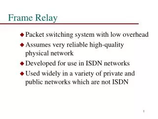
FRAME-RELAY. Frame-relay is a packet switching technology that offers fast flexible networking. Typical Frame-relay interfaces can operate at transmission rates ranging from 56 Kbps to 45 Mbps. Frame-relay provide high speed connections between widely dispersed Local Area Networks (LAN’s).

E N D
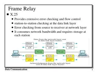
Frame-relay is a packet switching technology that offers fast flexible networking. Typical Frame-relay interfaces can operate at transmission rates ranging from 56 Kbps to 45 Mbps. Frame-relay provide high speed connections between widely dispersed Local Area Networks (LAN’s). Frame-relay is a connection oriented service, it creates logical connections called Permanent Virtual Circuits (PVC’s) between the sending and receiving router interfaces. A PVC defines the route that the frame will take when travelling between stations on a frame-relay network. The PVC between any two stations on a frame-relay network is identified by a number known as a Data Link Connection Identifier (DLCI) on each end of the PVC. What is Frame-relay
A single physical interface on a router can have many PVC’s with each PVC going to a different destination, but each of these PVC’s must have a unique DLCI associated with it. The DLCI is locally significant on the router and can be any number between 16 – 1007. The DLCI can be assigned manually, it is then known as a static DLCI. Or the DCLI can be obtained from the frame switch automatically using inverse-arp, then its known as a dynamic DLCI. A frame-relay pvc can have three possible values, active, inactive or deleted. You can use the show frame-relay pvc command from privileged mode to view information regarding the PVC’s and DLCI’s. What is Frame-relay
The frame-relay LMI (local management interface) is used by the customer to monitor the link between their router (DTE) and the service providers frame switch (DCE) There are three types of frame-relay LMI, they are Cisco, ANSI and q933a The local management interface communicates over specific DLCI’s Cisco uses DLCI 1023 whilst both ANSI and q933a use DLCI 0 LMI status messages combined with Inverse ARP messages allow a router to associate network layer ip addresses and data link layer DLCI addresses. When a router that is connected to a frame-relay network is started, it sends an LMI status inquiry message to the frame switch The frame switch replies with an LMI status message containing details of every virtual circuit configured on the access link. Frame-relay LMI
The frame switch is nearly always the property of the service provider, and as such is there responsibility to configure. Its job is simply to switch frame-relay encapsulated frames entering one port (the ingress port) to the correct exiting port (egress port). It does this by having a pre-defined set of routes configured that map an incoming frames DLCI to an outgoing switch port, these frame-relay routes can become quite extensive. It is possible to make a Cisco router operate as a frame switch, by entering the command frame-relay switching, which will cause it to switch frames at Layer 2 instead of switching IP packets at Layer 3. This is very useful for lab configurations as it allows you to experience the full range of frame-relay configuration examples. The Frame Switch
Configure terminal frame-relay switching interface Serial1 no ip address encapsulation frame-relay clock rate 64000 frame-relay intf-type dce frame-relay route 102 interface Serial2 201 frame-relay route 103 interface Serial3 301 frame-relay route 104 interface Serial4 401 frame-relay route 105 interface Serial5 501 frame-relay route 106 interface Serial6 601 frame-relay route 107 interface Serial7 701 frame-relay route 108 interface Serial8 801 frame-relay route 109 interface Serial9 901 The Frame Switch
Set the layer 2 (data-link layer) encapsulation to frame-relay on the physical interface, using the interface configuration mode command encapsulation frame-relay [ cisco | ietf ] Enter the command no frame-relay inverse-arp to stop the router automatically mapping all the DLCI’s that exist on the frame switch. Allow the interface to send and receive frame-relay frames by entering no shutdown. In the real world it is best to create sub-interfaces, then apply the layer 3 configuration (IP addresses) to these sub-interfaces. Using point-to-point sub-interfaces stops the problem known as split-horizon which can destroy the routing process in your network. Finally on the point-to-point sub-interface you define the out-going DLCI using the frame-relay interface-dlci command. Frame-relay step by step