Download
1 / 24
270 likes | 732 Views
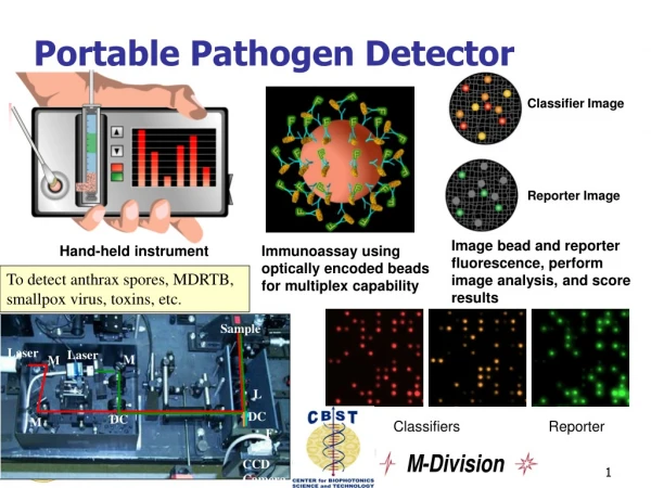
Portable NMR Detector. May 29, 2005 Ryan Hubbard David Ng. Relevance of Work. Current NMR/MRI devices are bulky and expensive Impossible to use in the field Most students never get hands on experience. Project Goals.

E N D
Portable NMR Detector May 29, 2005 Ryan Hubbard David Ng
Relevance of Work • Current NMR/MRI devices are bulky and expensive • Impossible to use in the field • Most students never get hands on experience
Project Goals • Create a small, relatively inexpensive, detector compatible with current NMR/MRI instrumentation • Device must be small and light enough for one person to carry • Device should have sufficiently small line width to resolve different chemicals (10ppm)
The Science of Spin • Protons act as tiny magnets • When an external field (B0) is applied, protons align with or against the field • A slight majority align with the field, so there is a net magnetization in the direction of B0
The Science of Spin • By applying an orthogonal, oscillatory field with an inductor, we can tip the magnetization into the plane of the inductor. • This vector then precesses like a gyroscope, creating a changing net magnetic field. • By Faraday’s Law, this creates a voltage signal in our inductor. ω = γB0 γ = 42.58 MHz/T for protons
Design: Instrumentation • Originally, we planned to use a Techmag Apollo controlled with NTNMR software under WIN2k. Under testing, this proved very unreliable. • Instead, we moved to a Varian system controlled with its own software running on a Sun platform.
Design: Switch • We use the same coil to create our orthogonal field as we do to receive the signal, so a transmit/receive switch is needed • Initially we used crossed diodes and a λ/4 cable, but the signal bled through our diodes, causing artifacts • The Varian system has an integrated switch, which only requires the addition of a proper λ/4 cable
Design: RF Coil • Induces precession of protons, and detects generated signal • LC Resonator, with variable capacitors for impedance matching and tuning • Tuned to frequency of precession. For the .64 T magnet ~ 27 MHz
Design: Magnets “Little Boy” • ~.6 T B0 • Four layers of 8 NdFeB magnets in a circular Halbach array “Fat Man” • ~1.1 T B0 • 36 magnets in 18 rods forming a hexagonal Halbach array
Fabrication: RF Coil • The inductor was hand wound, then soldered into place on a PCB along with non-magnetic capacitors and the co-axial cable • The coil was then manually tuned to a frequency slightly below the frequency of precession using a spectrum analyzer • A free-space coil was constructed for “Fat Man”, to eliminate any possible noise caused by the large copper PCB
Fabrication: “Little Boy” • Four magnet “sandwiches,” 8 magnets per layer • All 32 magnets characterized and specifically placed to optimize homogeneity • 4 magnets were epoxied onto each plate, and the two plates were then epoxied together using bolts to keep them centered • Finally, the four layers were stacked together to create the whole magnet. • Teflon runners epoxied to the brass bore plating were used to mount the coil inside the magnet.
Fabrication: “Fat Man” • Each magnet characterized as before • Two matched magnets aligned and epoxied into each tube • Each tube specifically placed to optimize efficiency • Tubes aligned using notched caps on each end, and held in place using set screws • Unfortunately, magnets are stronger than the aluminum keys used to align them, resulting in breakage
Testing: Factors • Pulse Width Adjustment: Is the signal really an FID? • Various Sample Materials: Can the detector differentiate substances? • Various Sample Sizes: How do the dimension of the sample affect amplitude and line width? • Power Adjustment: How do amplitude and line width change? • Coil Position: How homogenous is the detector? • Tolerance: How do changes in coil tuning affect output?
PW Adjustment • Varying the pulse width adjusts the degree to which the net magnetization is projected onto the XY plane • This is sinusoidal, with the magnetization tipping further onto the XY plane, and then rotating further past it.
Various Materials Ultrasound Gel Epoxy Pt. A Epoxy Pt. B Vaseline Empty Plastic Chamber Air Teflon Stage
Various Materials • Line width is too broad for proton rich samples, so different materials cannot be differentiate • The 50% bandwidth of 5 kHz indicates a ΔB0 of 11.74 G • However, signal amplitude is an order of magnitude lower in samples without protons • Essentially what we have is a proton counter • Note that there is a constant frequency artifact near 27.07 MHz due to noise
Power Comparison • Power adjustments do not seem to have an appreciable effect on signal amplitude or bandwidth • Signal amplitude is directly proportional to the net magnetization due to B0, so it should be independent of the RF pulse Higher Power Full Sample Higher Power Small Sample
Sample Sizes • Amplitude approximately proportional to signal size • Bandwidth decreases for smaller samples, but also geometry dependent • Lower limit on bandwidth appears to be 1.57 kHz, ~ 58ppm
Homogeneity • Signal is strongest in the center of the magnet (Highest B0) • It is slightly more homogenous at 3mm away from the center, but much worse outside that range
Tolerance • Decreasing peak attenuation by adjusting variable capacitors had no significant effect on results, once again because signal strength is mostly dependent B0 Peak attenuation -10dB • Detuning the coil by adjusting variable capacitors to shift frequency reduced signal strength, because fewer protons are precessing at this frequency.
Future Improvements • Fat Man – Close to Clinical MRI Strength • Shimming – Increase Homogeneity • Compact Instrumentation – True Portability • Free Space Coil – More Stable System • Gradient Coils – Imaging Applications • Spin-Echo Sequences – Negates some in-homogeneities in imaging • Shielding Against Noise
Thanks • Dr. Luisa Ciobanu, Dr. Boris Odintsou, Dr. Andrew Webb, Mary Jane Ham, Mikhail and everyone at BIC for use of their facilities and experience • Scott Mc Donald and Scott Sprague for all our machine work • Frank Dale and the ECE Shop for parts • Shenghui Zhang for general assistance
References • J.P. Hornak “Spin Physics” The Basics of NMR (J.P. Hornak, 1997) • G. Moresi & R. Magin “Miniature Permanent Magnet for Table-top NMR” Concepts in Magnetic Resonance Part B, Vol. 19B(1) pg. 35-43 (Wiley Periodicals, 2003) • H. Raich, P. Blümler “Design and Construction of a Diploar Halbach Array with a Homogeneous Field from Identical Bar Magnets: NMR Mandhalas” Concepts in Magnetic Resonace Part B, Vol. 23B(1) pg. 16-25 (Wiley Periodicals, 2004)