Download
1 / 21
210 likes | 397 Views
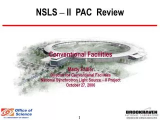
NSLS – II EFAC Review. Conventional Facilities Briefing Marty Fallier Director for Conventional Facilities National Synchrotron Light Source – II Project October 19, 2006. Outline. Conventional Facilities Scope Facility Overview Facility Program Experimental Floor

E N D
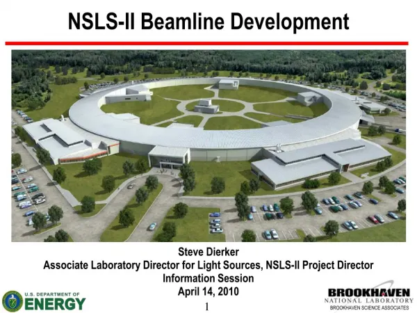
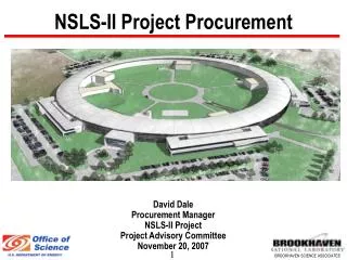
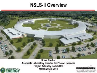
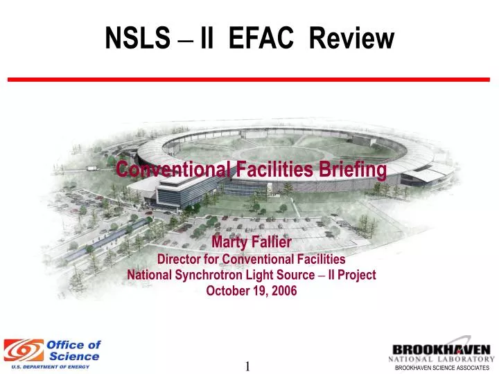
NSLS – II EFAC Review Conventional Facilities Briefing Marty Fallier Director for Conventional Facilities National Synchrotron Light Source – II Project October 19, 2006
Outline • Conventional Facilities Scope • Facility Overview Facility Program • Experimental Floor • Central Lab Office Building • Lab Office Building(s) • Differential Settlement • Vibration Mitigation • Utility Services • Temperature Stability • Schedule
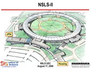
Site Plan NSLS Conf. Center Service Bldg Typ 4 CLOB CFN Future JPsi RF-LINAC AREA Future Guest House LOB Typ 4 Ring Bldg Loading Underpass
Experimental Floor Concept • Divided into 5 clusters • Service Bldg supports all services within the cluster • Six sectors/Cluster • CLOB & Service Bldgs contain all Accelerator systems • Ring, CLOB, LOB 1 & service bldgs are base scope • LOB’s 2,3,4 can be added as needed w/o interruption
CLOB Features • Space for 190 Offices, 8 labs • Nominally 30 User Offices, 5 User labs from the total • Possible 400 seat Conference Center addition w/ vendor area and three breakout rooms • Lobby and User Reception area • 2nd floor viewing gallery overlooking experimental floor • Bridge to electrical mezzanine and control room & RF/LINAC areas • Close Proximity to future: • JPSI Building • Guest house
LOB Features • Modular design – can be added when needed without interrupting operation • 11,000 SF each – Serves six sectors • 30 offices w/ conference space, interaction areas, lavs, showers • 5 labs intended for shared use • Shipping/Receiving/Storage area & chemical storage area • Potential for expansion for more offices if needed • Egress provided for personnel and large items at each LOB • Loading area with exterior roll-up door • Roll-up door from each lab onto the experimental floor • Designed to minimize impacts to future long beamlines
Differential Settlement • Measures to reduce potential for differential settlement include: • Thorough geotechnical analysis of site to identify problem areas • Minimize footprint over disturbed areas • Set finished floor elevation for maximum cut and minimum fill • Early site preparation contract for maximum time to cut, fill, compact and observe settlement prior to building contract. • Monolithic slab design for tunnel and experimental floor • High slab stiffness, Tunnel 36”; Experimental Floor 18” • Building loads isolated from tunnel and experimental floor slab • Access corridor isolated from experimental floor slab
Vibration Mitigation • Measures to be implemented in conventional design include: • “Monolithic” slab for accelerator and experimental floor • Slab thickness and section changes will be based on vibration modeling results • Possible use of polymer admixtures for enhanced damping characteristics – likely use for access corridor • Isolation of bldg structure from tunnel and slab • Inertial bases and isolation of machinery • Low flow velocity design for ducts and piping • Limited use of duct and piping isolation to avoid conversion & transmission of low frequency vibration • Commissioning of equipment and systems to include alignment, balancing & vibration measurement
Utility Support • Utilities run underground in center of ring and distributed to five service bldgs (one in CLOB RF/LINAC area) • Minimizes pipe runs and pipe size in bldg proper • Only needed service piping will be run in experimental area • Minimizes potential noise and vibration impacts • Services provided at each BL include: • Electric Power Panel at Ratchet Wall, 75-95kW/Cell, 120/208V • Cooling Water, HVAC Supply Air, Exhaust • Compressed Air, LN2, GN2 • DI Water (Copper and Aluminum) by Accelerator Group
Temperature Stability • Key temperature stability requirement is tunnel air @ +/- 0.1C at a given location with respect to time. • Requires high resolution industrial grade instruments and controls with excellent repeatability. • Space temp setpoint of 85 F is nominally equivalent to process cooling water supply setpoint to minimize temperature gradients • Should be readily achievable provided loads to accelerator components are relatively steady-state • Experimental Floor Temperature • Cooling: 75 F +/- 1 F, 50% RH +/- 10% RH • Heating: 75 F +/- 1F, 30% RH +/- 10% RH
Schedule • Construction sequencing will enable • Availability of Ring Bldg for LINAC, booster and storage ring installation to begin as early as March 2010 • Beneficial Occupancy of Ring Building & LOB - June 2011 • Control/Computer room availability & CLOB BO - August 2011 • Conventional Construction complete - October 2011