Download
1 / 14
150 likes | 370 Views
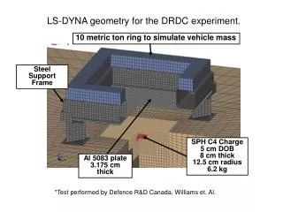
Container Impact in Water Using LS-DYNA. Matt Wesley mwesley@hawaii.edu University of Hawaii at Manoa 7/6/12. Outline. Beginning stages Model setups Results so far Future work. Beginning Steps. Learning to use LS-DYNA Running SMP or MPP

E N D
Container Impact in Water Using LS-DYNA Matt Wesley mwesley@hawaii.edu University of Hawaii at Manoa 7/6/12
Outline • Beginning stages • Model setups • Results so far • Future work
Beginning Steps • Learning to use LS-DYNA • Running SMP or MPP • shared memory parallel or massive parallel processing
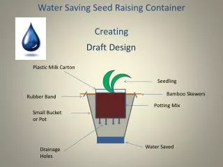
Side view Model Setup 20.4 in 48 in • Need an accurate model to test in air and in water • 1:5 scale of a 20ft shipping container • Made from acrylic 48.5 in
Solid or Shell Elements • Shell elements yield even at low velocities • Solid elements hold up much better
Acrylic Box Model • Material: PLASTIC_KINEMATIC • E=3.2 GPa • ρ=1200 kg/m3 • ν=0.37 • Dimensions: • Base: modeled as solid elements, thickness of 0.024 m • Base also has a lip, this is where the contact will be made • Top: modeled as shell elements, thickness of 0.012 m
Contact • First, created a wall with the same width as the box • Used rigid material • Set it to be stationary • Next, created a ‘load cell’ • Used the same rigid material and made it stationary • Varied the speed at which the box impacted
Model verification • *A*v • When contact area is the whole base: • Fact = 39800N • Fest = 39504N • This is using an adjusted density of 3560 kg/m3
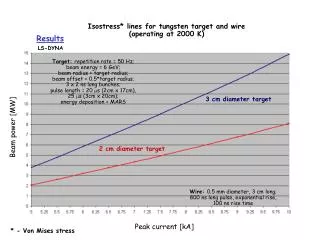
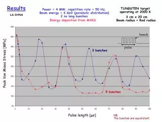
Impact forces on a 0.1016m diameter cylinder Estimation uses adjusted density of 5893 kg/m3
OSU test setup • Viscous flow with an initial velocity • BIG!!! • Need to add a column with a ‘load cell’ and the acrylic box model • Just using basic properties for now until the model works
Problems • Need to void the interior of the box • *INITIAL_VOLUME_FRACTION_GEOMETRY • What is the best ratio of ALE nodes per Lagrangian node • Long run times!!!
Conclusion • Starting out with LS-DYNA • Results so far • Future work and problems
Sources • Paczkowski, K. Riggs, H.R. Naito, C.J. Lehmann, A. A one-dimensional model for impact forces resulting from high mass, low velocity debris. Structural Engineering and Mechanics. Vol. 42. No. 6. 2012. Pages 831-847. • http://www.encyclopedia2.thefreedictionary.com/MPP • LS-DYNA Theory Manual