Download
1 / 26
260 likes | 506 Views
Chapter 5, Analysis: Dynamic Modeling. Outline. Dynamic modeling Sequence diagrams State diagrams Using dynamic modeling for the design of user interfaces Analysis example Requirements analysis document template. Dynamic Modeling with UML. Diagrams for dynamic modeling

E N D
Outline • Dynamic modeling • Sequence diagrams • State diagrams • Using dynamic modeling for the design of user interfaces • Analysis example • Requirements analysis document template
Dynamic Modeling with UML • Diagrams for dynamic modeling • Interaction diagrams describe the dynamic behavior between objects • Statecharts describe the dynamic behavior of a single object • Interaction diagrams • Sequence Diagram: • Dynamic behavior of a set of objects arranged in time sequence. • Good for real-time specifications and complex scenarios • Collaboration Diagram : • Shows the relationship among objects. Does not show time • State Charts: • A state machine that describes the response of an object of a given class to the receipt of outside stimuli (Events). • Activity Diagram: • Special type of statechart where all states are action states
Dynamic Modeling • Definition of dynamic model: • A collection of multiple state chart diagrams, one state chart diagram for each class with important dynamic behavior. • Purpose: • Detect and supply methods for the object model • How do we do this? • Start with use case or scenario • Model interaction between objects => sequence diagram • Model dynamic behavior of single objects => statechart diagram
What is an Event? • Something that happens at a point in time • Relation of events to each other: • Causally related: Before, after, • Causally unrelated: concurrent • An event sends information from one object to another • Events can be grouped in event classes with a hierarchical structure.
Sequence Diagram • Relation to object identification: • Objects/classes have already been identified during object modeling • Objects are identified as a result of dynamic modeling • Heuristic: • An event always has a sender and a receiver. Find them for each event => These are the objects participating in the use case
Heuristics for Sequence Diagrams • Layout: • 1st column: Should correspond to the actor who initiated the use case • 2nd column: Should be a boundary object • 3rd column: Should be the control object that manages the rest of the use case • Creation: • Control objects are created at the initiation of a use case • Boundary objects are created by control objects • Access: • Entity objects are accessed by control and boundary objects, • Entity objects should never call boundary or control objects: This makes it easier to share entity objects across use cases and makes entity objects resilient against technology-induced changes in boundary objects.
Statechart Diagrams • Graph whose nodes are states and whose directed arcs are transitions labeled by event names. • Distinguish between two types of operations: • Activity: Operation that takes time to complete • associated with states • Action: Instantaneous operation • associated with events • associated with states (reduces drawing complexity): Entry, Exit, Internal Action • A statechart diagram relates events and states for one class • An object model with a set of objects has a set of state diagrams
State • An abstraction of the attribute of a class • State is the aggregation of several attributes a class • Basically an equivalence class of all those attribute values and links that do no need to be distinguished as far as the control structure of the system is concerned • Example: State of a bank • A bank is either solvent or insolvent • State has duration
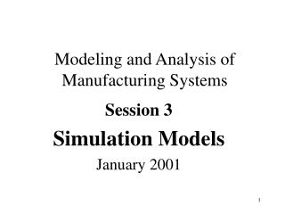
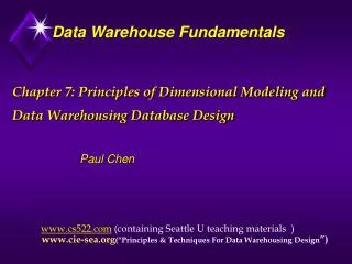
UML Statechart Diagram Notation Event trigger With parameters State1 State2 Event1(attr) [condition]/action do/Activity Guard condition entry /action exit/action Also: internal transition and deferred events
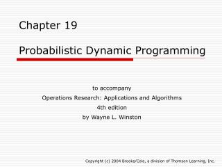
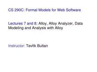
Example of a StateChart Diagram coins_in(amount) / set balance Collect Money Idle coins_in(amount) / add to balance cancel / refund coins [item empty] [select(item)] [change<0] do: test item and compute change [change>0] [change=0] do: dispense item do: make change
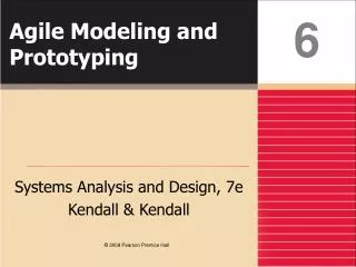
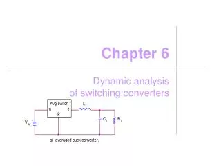
Expanding activity “do:dispense item” ‘Dispense item’ as an atomic activity: [change=0] do: dispense item ‘Dispense item’ as a composite activity: do: push item off shelf do: move arm to column do: move arm to row Arm ready Arm ready
Dynamic Modeling of User Interfaces • Statechart diagrams can be used for the design of user interfaces • Also called Navigation Path • States: Name of screens • Graphical layout of the screens associated with the states helps when presenting the dynamic model of a user interface • Activities/actions are shown as bullets under screen name • Often only the exit action is shown • State transitions: Result of exit action • Button click • Menu selection • Cursor movements • Good for web-based user interface design
Let’s Do Analysis 1. Analyze the problem statement • Identify functional requirements • Identify nonfunctional requirements • Identify constraints (pseudo requirements) 2. Build the functional model: • Develop use cases to illustrate functionality requirements 3. Build the dynamic model: • Develop sequence diagrams to illustrate the interaction between objects • Develop state diagrams for objects with interesting behavior 4. Build the object model: • Develop class diagrams showing the structure of the system
Requirements Analysis Document Template 1. Introduction 2. Current system 3. Proposed system 3.1 Overview 3.2 Functional requirements 3.3 Nonfunctional requirements 3.4 Constraints (“Pseudo requirements”) 3.5 System models 3.5.1 Scenarios 3.5.2 Use case model 3.5.3 Object model 3.5.3.1 Data dictionary 3.5.3.2 Class diagrams 3.5.4 Dynamic models 3.5.5 User interface 4. Glossary
Section 3.5 System Model 3.5.1 Scenarios - As-is scenarios, visionary scenarios 3.5.2 Use case model - Actors and use cases 3.5.3 Object model - Data dictionary - Class diagrams (classes, associations, attributes and operations) 3.5.4 Dynamic model - State diagrams for classes with significant dynamic behavior - Sequence diagrams for collaborating objects (protocol) 3.5.5 User Interface - Navigational Paths, Screen mockups
Section 3.3 Nonfunctional Requirements 3.3.1 User interface and human factors 3.3.2 Documentation 3.3.3 Hardware considerations 3.3.4 Performance characteristics 3.3.5 Error handling and extreme conditions 3.3.6 System interfacing 3.3.7 Quality issues 3.3.8 System modifications 3.3.9 Physical environment 3.3.10 Security issues 3.3.11 Resources and management issues
Nonfunctional Requirements: Trigger Questions 3.3.1 User interface and human factors • What type of user will be using the system? • Will more than one type of user be using the system? • What sort of training will be required for each type of user? • Is it particularly important that the system be easy to learn? • Is it particularly important that users be protected from making errors? • What sort of input/output devices for the human interface are available, and what are their characteristics? 3.3.2 Documentation • What kind of documentation is required? • What audience is to be addressed by each document? 3.3.3 Hardware considerations • What hardware is the proposed system to be used on? • What are the characteristics of the target hardware, including memory size and auxiliary storage space?
Nonfunctional Requirements (continued) 3.3.4 Performance characteristics • Are there any speed, throughput, or response time constraints on the system? • Are there size or capacity constraints on the data to be processed by the system? 3.3.5 Error handling and extreme conditions • How should the system respond to input errors? • How should the system respond to extreme conditions? 3.3.6 System interfacing • Is input coming from systems outside the proposed system? • Is output going to systems outside the proposed system? • Are there restrictions on the format or medium that must be used for input or output?
Nonfunctional Requirements, ctd • 3.3.7 Quality issues • What are the requirements for reliability? • Must the system trap faults? • Is there a maximum acceptable time for restarting the system after a failure? • What is the acceptable system downtime per 24-hour period? • Is it important that the system be portable (able to move to different hardware or operating system environments)? • 3.3.8 System Modifications • What parts of the system are likely candidates for later modification? • What sorts of modifications are expected? • 3.3.9 Physical Environment • Where will the target equipment operate? • Will the target equipment be in one or several locations? • Will the environmental conditions in any way be out of the ordinary (for example, unusual temperatures, vibrations, magnetic fields, ...)?
Nonfunctional Requirements, ctd • 3.3.10 Security Issues • Must access to any data or the system itself be controlled? • Is physical security an issue? • 3.3.11 Resources and Management Issues • How often will the system be backed up? • Who will be responsible for the back up? • Who is responsible for system installation? • Who will be responsible for system maintenance?
Pseudo Requirements (Constraints) • Pseudo requirement: • Any client restriction on the solution domain • Examples: • The target platform must be an IBM/360 • The implementation language must be COBOL • The documentation standard X must be used • A dataglove must be used • ActiveX must be used • The system must interface to a papertape reader
Summary In this lecture, we reviewed the construction of the dynamic model from use case and object models. In particular, we described: In particular, we described: • Sequence diagrams for identifying missing objects and operations. • Statechart diagrams for identifying missing attributes. • Definition of an event hierarchy. In addition, we described the requirements analysis document and its use when interacting with the client.