Download
1 / 58
800 likes | 1.69k Views
ELECTRICAL PROPERTIES OF CABLE INSULATION MATERIALS. BRUCE S. BERNSTEIN. Paper-Insulated Lead Covered Cables. PILC-Fundamentals. MEDIUM VOLTAGE Polyethylene[PE] Crosslinked PE [XLPE] Tree Retardant Crosslinked PE [TR-XLPE] Ethylene-Propylene Elastomers [EPR] PILC. HIGH VOLTAGE

E N D
ELECTRICAL PROPERTIESOFCABLE INSULATION MATERIALS BRUCE S. BERNSTEIN
Paper-Insulated Lead Covered Cables PILC-Fundamentals
MEDIUM VOLTAGE Polyethylene[PE] Crosslinked PE [XLPE] Tree Retardant Crosslinked PE [TR-XLPE] Ethylene-Propylene Elastomers [EPR] PILC HIGH VOLTAGE Crosslinked Polyethylene PAPER/OIL Paper/Polypropylene [PPP] SF6 Gas INSULATION MATERIALS
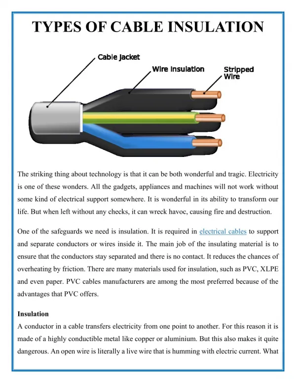
PILC • Cable is comprised of Paper strips wound over conductor with construction impregnated with dielectric fluid (oil) • Long Service History • Reliable/used since late 1800s • Gradually being replaced by Extruded Cables
PILC • Paper derived form wood • Wood • Cellulose 40% • Hemicellulose 30% Poor Electrical Properties • Lignin 30% Serves as adhesive • Cellulose must be separated from others • Separation by bleaching • sulfate/sulfite process
PILC • CELLULOSE-Insulation Material • HEMICELULOSE-Non-fibrous • more polar • losses higher vs. cellulose • LIGNIN-Amorphous • binds other components in the wood
Paper/Oil • Cellulose chemical structure more complex vs. PE or XLPE • Oil impregnates the cellulose/superior dielectric properties • Different cable constructions for Medium vs. High Voltage
Paper/Oil • LEAD SHEATH over cable construction • Protects cable core • Benefit: Superior barrier to outside environment
COMPARISON OF CABLE INSULATION MATERIALS PE / XLPE / TR-XLPE /EPR / PILC
Polyethylene • Low Permittivity: limits capacitive currents • Low Tan Delta: Low Losses • Very High dielectric strength (prior to aging) • Easy to process/extrude
Crosslinked Polyethylene • All of the above PLUS • Improved mechanical properties at elevated temperature • does not melt at 105°C and above • thermal expansion • Improved water tree resistance vs. PE
Tree-retardant XLPE • All of the above PLUS • Superior Water tree resistance to XLPE • TR-XLPE properties brought about by • Additives to XLPE • Modifying the PE structure before crosslinking • Both
Paper/Oil PILC • Long history of reliability • some cables installed 60 or more years ! • More tolerant of some common diagnostic tests to ascertain degree of aging • DC testing
EPR • Compromise of extruded cable properties • Permittivity, Tan Delta > XLPE’s • Dielectric strength slightly lower • High temperature properties : • Equal to or > XLPE’s
Advantages of Extruded Cables • Reduced Weight vs. Paper/Oil • Accessories more easily applied • Easier to repair faults • No hydraulic pressure/pumping requirements • Reduced risk of flammability/propagation • Economics • Initial and lifetime costs
Extruded Cables at High Temperatures • PE/XLPE/TR-XLPE • At elevated temperatures, crystalline regions start to melt • Thermal expansion • Physical/mechanical strength reduced • At 105°C crystallinity gone: • PE flows • XLPE and TR-XLPE crosslinking allows for maintenance of FORM stability • At high temperatures, crosslinks substitute for the crystallinity at low temperature
Extruded Cables at High Temperature • PE/XLPE/TR-XLPE • Although Crosslinks serve as Crystallinity substitute, they do NOT provide same degree of • toughness • moisture resistance • Impact resistance • Crosslinking assists in maintaining form stability, but not mechanical properties • Physical/electrical properties change as temperature increases
Extruded Cables at High Temperature • EPR • Little to no crystallinity initially • Form stability maintained due to presence of inorganic mineral filler (clay) • Physical and electrical properties change to some extent as temperature is increased • Present day issue: operating reliability at higher temperatures vs. semicrystalline polymer insulation
Paper/Oil at High Temperature • Cellulose: No significant thermal expansion • compare with extruded cables • Oil: Some thermal expansion • Degradation mechanisms differ at elevated temperature
Paper/Oil Cellulose degradation consistent from batch to batch Starts to degrade immediately under thermal stress Moisture evolves Follows Arrhenius model Oil may form wax over time(Polymerization) Extruded Degradation is polymer structure related Degradation related to antioxidant efficiency Does not start until stabilization system affected No water evolution No proven model exists Thermal Degradation
Natural Polymer Carbon/Hydrogen/Oxygen More polar Not Crosslinked Linear Fibrils/no thermal Expansion Oil expands thermally Thermal degradation of cellulose at weak link (C-O) DC : No harmful Effect on Aged cable-does remove weak link Summary: Paper/Oil
Synthetic Polymer Carbon/Hydrogen Less Polar Branched chains Non-fibril Partly crystalline: much less for EPR Mineral fillers (EPR) Thermal expansion on heating Crosslinked Degrades at weakened regions/crosslinks ‘hold together’ form stability DC: Latent problem -effect depends on age (XLPE) Summary: Extruded Materials
Electrical Properties ___________________Determined By Physical and Chemical Structure
Electrical Properties of Polyolefins • The Electrical Properties of Polyolefins may be separated into two categories: • Those observed at low electric field strengths • Those at very high field strengths • LOW FIELD • Dielectric constant/dissipation factor • Conductivity • Determines how good a dielectric is the insulation • HIGH FIELD • -Partial discharges (corona) • Controls functioning and reliability
How does Polymer Insulation Respond to Voltage Stress • Polar Regions tend to migrate toward electrodes • Motion Limited • Insulation becomes slightly ‘mechanically stressed’ • Charge is stored • Properties change • Next few slides seek to picture events in idealized terms
POLARIZATION OF A POLYMER THAT CONTAINSMOBILE CHARGE CARRIERS + Polymer Polymer – No field DC field applied, polymer becomes polarized
ORIENTATION OF POLYMERUPON APPLICATION OF VOLTAGE STRESSAlignment of Charge Carriers Electrode Polymer Electrode Electrode Polymer Electrode
IDEALIZED DESCRIPTIONorientation of polar functionality of polymer chains under voltage stress No Voltage Voltage Stress Applied
POLARIZATION OF A POLYMER THAT CONTAINSSIDE GROUPS WITH PERMANENT DIPOLES No field field applied, polymer becomes polarized
SCHEMATIC OF SOME NORMAL MODESOF MOTION OF A POLYMER CHAIN Third Mode First Mode Second Mode
Application of Low Voltage Stress • Dielectric Constant:Ability to ‘hold’ charge • Lower Polarity -> Lower K • Dissipation Factor: Losses that occur as a result of energy dissipated as heat, rather than electrical energy • > Polarity leads to > Losses
DC vs. AC Under DC- Polarization persists Under AC-Constant motion of the polymer segments due to changing polarity
Dielectric Constant • TECHNICAL DEFINITION • In a given medium (e.g. for our purposes, in a specific polymer insulation)—it is the Ratio of • (a) the quantity of energy that can be stored, to • (b) the quantity that can be stored in a vacuum
Dielectric Constant • Relatively small if no permanent dipoles are present • Approximately proportional to density • Influenced by presence of permanent dipoles: • Dipoles orient in the electric field • inversely proportional to temperature • Orientation requires a finite time to take place • is dependent upon frequency • Relaxation time for orientation of a dipole is also temperature dependent
Dielectric Constant • The dielectric constant of the electrical-insulating materials ranges from: • a low of about 2 or less for materials with lowest electrical-loss characteristics, • up to 10 or so for materials with highest electrical losses
Polyethylene 2.28 Polypropylene 2.25 Butyl Rubber 2.45 Poly MMA 2.7-3.2 Nylon 66 3.34 PPLP (Oil-Impregnated) 2.7 Sources: M.L.Miller “Structure of Polymers”, Dupont and Tervakoski Literature Cellulose Acetate 3.2-7.0 PVC 2.79 Mylar (Polyester) 3.3 Kapton (Polyimide) 3.6 Nomex (Polyamide) 2.8 Cyanoethylcellulose 13.3 Dielectric Constant of Common Polymers
DIELECTRIC LOSSES • From a materials perspective, losses result from polymer chain motion • Leads to heat evolution • Chain motion influence on electrical properties are depicted on next few slides
’ AND ” AS A FUNCTION OF FREQUENCY ’ log ” max log
Dispersion • Dipoles RIGIDLY attached - oriented by MAIN chain motion • Dipoles FLEXIBLY attached - orientation of pendant dipoles and/or orientation by chain segmental motion (shows TWO dispersion regions) at different frequencies • PE that has been OXIDIZED • PE that is a copolymer with polar monomer, e.g., SOME TR-XLPE Note: 60Hz is not necessarily where these phenomena show maxima
Electrical Properties of PolyolefinsPoly Olefin Structure and Dielectric Behavior • The electrical behavior of insulating materials is influenced by temperature, time, moisture and other contaminants, geometric relationships, mechanical stress and electrodes, and frequency and magnitude of applied voltage. These factors interact in a complex fashion. • Saturated hydrocarbons are non-polar • Dielectric constants are low • Dielectric constants essentially frequency-independent (if pure) • Dielectric constants change little with temperature The change that occurs is related to density changes
ELECTRIC BREAKDOWN • INABILITY OF INSULATION TO OPERATE or HOLD CHARGE UNDER STRESS • Insulation inherent properties • Thermal • Stream of electrons released • Discharge- • Preceded by Partial Discharge
Electric BreakdownTypes of Breakdown • Failure of a material due to the application of a voltage stress • called the dielectric strength • expressed as kV/mm or V/mil • Electric breakdown occurs when the applied voltage can no longer be maintained across the material in a stable fashion without excessive flow of current and physical disruption • Theoretical understanding not clear even now • What is clear is that there are several mechanisms of failure
Electric BreakdownTypes of Breakdown Intrinsic Breakdown • Defined by the characteristics of the material itself in pure and defect-free form under test conditions which produce breakdown at the highest possible voltage. Never achieved experimentally. Thermal Breakdown • Occurs when the rate of heating exceeds the rate of cooling by thermal transfer and thermal runaway occurs under voltage stress
Electric BreakdownTypes of Breakdown Discharge-Induced Breakdown • Occurs when electrical discharges occur on the surface or in voids of electrical insulation. Ionization causes slow degradation. Corona, or partial discharge, is characterized by small, local electrical discharges Treeing-Electrical • Results from partial discharge
AC Breakdown Strength of 15 kV XLPE Cable Vs. Position on Cable Run For One 5000 Foot Reel of 50,000 Foot Run
WEIBULL • Commonly used to characterize time to failure information • Defines • Characteristic Time to Failure • Scale Factor/ 63.2% probability of failure • Shape parameter/slope of failure times • Called two parameter Weibull distribution • Controversial: “Most physical models do predict this type of distribution for failure as a function of time (but not necessarily of voltage stress”) Dissado and Fothergill, Page 323
Short-Time Voltage Breakdown of Polyethylene AC and DC at -196°C DC at room temperature AC (60 Hz) at room temperature
Dielectric StrengthImportant Points to Remember ! • AC breakdown strength value NOT absolute • Related to rate of rise of the applied voltage stress • 5 minute step rise • 10 minute step rise • 30 minute step rise • Ramp • Real world/stress is constant • Voltage endurance
Electric BreakdownTypes of Breakdown Treeing- Water • Water tree growth induced by water in presence of voltage stress. Water trees generate at much lower stresses than electrical trees. Not a direct cause of breakdown