Download

1 / 62
1.16k likes | 2.48k Views
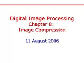
Digital Image Processing Chapter 5: Image Restoration 23 June 2006. Concept of Image Restoration. Image restoration is to restore a degraded image back to the original image while image enhancement is to manipulate the image so that it is suitable for a specific application.

E N D
Digital Image Processing Chapter 5: Image Restoration 23 June 2006
Concept of Image Restoration Image restoration is to restore a degraded image back to the original image while image enhancement is to manipulate the image so that it is suitable for a specific application. Degradation model: whereh(x,y)is a system thatcauses image distortion and h(x,y) is noise. (Images from Rafael C. Gonzalez and Richard E. Wood, Digital Image Processing, 2nd Edition.
Noise Models Noise cannot be predicted but can be approximately described in statistical way using the probability density function (PDF) Gaussian noise: Rayleigh noise Erlang (Gamma) noise
Noise Models (cont.) Exponential noise Uniform noise Impulse (salt & pepper) noise
PDF: Statistical Way to Describe Noise PDF tells how much each z value occurs. (Images from Rafael C. Gonzalez and Richard E. Wood, Digital Image Processing, 2nd Edition.
Image Degradation with Additive Noise Degraded images Original image Histogram (Images from Rafael C. Gonzalez and Richard E. Wood, Digital Image Processing, 2nd Edition.
Image Degradation with Additive Noise (cont.) Degraded images Original image Histogram (Images from Rafael C. Gonzalez and Richard E. Wood, Digital Image Processing, 2nd Edition.
Periodic Noise Periodic noise looks like dots In the frequency domain (Images from Rafael C. Gonzalez and Richard E. Wood, Digital Image Processing, 2nd Edition.
Estimation of Noise We cannot use the image histogram to estimate noise PDF. It is better to use the histogram of one area of an image that has constant intensity to estimate noise PDF. (Images from Rafael C. Gonzalez and Richard E. Wood, Digital Image Processing, 2nd Edition.
Periodic Noise Reduction by Freq. Domain Filtering Degraded image DFT Periodic noise can be reduced by setting frequency components corresponding to noise to zero. Band reject filter Restored image (Images from Rafael C. Gonzalez and Richard E. Wood, Digital Image Processing, 2nd Edition.
Band Reject Filters Use to eliminate frequency components in some bands Periodic noise from the previous slide that is Filtered out. (Images from Rafael C. Gonzalez and Richard E. Wood, Digital Image Processing, 2nd Edition.
Notch Reject Filters A notch reject filter is used to eliminate some frequency components. (Images from Rafael C. Gonzalez and Richard E. Wood, Digital Image Processing, 2nd Edition.
Notch Reject Filter: Notch filter (freq. Domain) Degraded image DFT (Images from Rafael C. Gonzalez and Richard E. Wood, Digital Image Processing, 2nd Edition. Noise Restored image
Example: Image Degraded by Periodic Noise Degraded image DFT (no shift) DFT of noise Noise Restored image (Images from Rafael C. Gonzalez and Richard E. Wood, Digital Image Processing, 2nd Edition.
Mean Filters Degradation model: To remove this part Arithmetic mean filter or moving average filter (from Chapter 3) Geometric mean filter mn = size of moving window
Geometric Mean Filter: Example Image corrupted by AWGN Original image Image obtained using a 3x3 geometric mean filter Image obtained using a 3x3 arithmetic mean filter AWGN: Additive White Gaussian Noise (Images from Rafael C. Gonzalez and Richard E. Wood, Digital Image Processing, 2nd Edition.
Harmonic and Contraharmonic Filters Harmonic mean filter Works well for salt noise but fails for pepper noise Contraharmonic mean filter mn = size of moving window Positive Q is suitable for eliminating pepper noise. Negative Q is suitable for eliminating salt noise. Q = the filter order For Q = 0, the filter reduces to an arithmetic mean filter. For Q = -1, the filter reduces to a harmonic mean filter.
Contraharmonic Filters: Example Image corrupted by pepper noise with prob. = 0.1 Image corrupted by salt noise with prob. = 0.1 Image obtained using a 3x3 contra- harmonic mean filter With Q = 1.5 Image obtained using a 3x3 contra- harmonic mean filter With Q=-1.5 (Images from Rafael C. Gonzalez and Richard E. Wood, Digital Image Processing, 2nd Edition.
Contraharmonic Filters: Incorrect Use Example Image corrupted by pepper noise with prob. = 0.1 Image corrupted by salt noise with prob. = 0.1 Image obtained using a 3x3 contra- harmonic mean filter With Q=-1.5 Image obtained using a 3x3 contra- harmonic mean filter With Q=1.5 (Images from Rafael C. Gonzalez and Richard E. Wood, Digital Image Processing, 2nd Edition.
Order-Statistic Filters: Revisit Original image subimage Statistic parameters Mean, Median, Mode, Min, Max, Etc. Moving window Output image
Order-Statistics Filters Median filter Max filter Reduce “dark” noise (pepper noise) Min filter Reduce “bright” noise (salt noise) Midpoint filter
Median Filter : How it works A median filter is good for removing impulse, isolated noise Salt noise Pepper noise Median Sorted array Moving window Degraded image Salt noise Filter output Pepper noise Normally, impulse noise has high magnitude and is isolated. When we sort pixels in the moving window, noise pixels are usually at the ends of the array. Therefore, it’s rare that the noise pixel will be a median value.
Median Filter : Example 1 2 Image corrupted by salt-and-pepper noise with pa=pb= 0.1 3 4 Images obtained using a 3x3 median filter (Images from Rafael C. Gonzalez and Richard E. Wood, Digital Image Processing, 2nd Edition.
Max and Min Filters: Example Image corrupted by pepper noise with prob. = 0.1 Image corrupted by salt noise with prob. = 0.1 Image obtained using a 3x3 max filter Image obtained using a 3x3 min filter (Images from Rafael C. Gonzalez and Richard E. Wood, Digital Image Processing, 2nd Edition.
Alpha-trimmed Mean Filter Formula: where gr(s,t) represent the remaining mn-d pixels after removing the d/2 highest and d/2 lowest values of g(s,t). This filter is useful in situations involving multiple types of noise such as a combination of salt-and-pepper and Gaussian noise.
Alpha-trimmed Mean Filter: Example 1 2 Image additionally corrupted by additive salt-and- pepper noise Image corrupted by additive uniform noise Image obtained using a 5x5 geometric mean filter 2 Image obtained using a 5x5 arithmetic mean filter 2 (Images from Rafael C. Gonzalez and Richard E. Wood, Digital Image Processing, 2nd Edition.
Alpha-trimmed Mean Filter: Example (cont.) 1 2 Image additionally corrupted by additive salt-and- pepper noise Image corrupted by additive uniform noise Image obtained using a 5x5 alpha- trimmed mean filter with d = 5 2 Image obtained using a 5x5 median filter 2
Alpha-trimmed Mean Filter: Example (cont.) Image obtained using a 5x5 arithmetic mean filter Image obtained using a 5x5 geometric mean filter Image obtained using a 5x5 alpha- trimmed mean filter with d = 5 Image obtained using a 5x5 median filter
Adaptive Filter General concept: • Filter behavior depends on statistical characteristics of local areas • inside mxn moving window • More complex but superior performance compared with “fixed” • filters Statistical characteristics: Noise variance: Local mean: Local variance:
Adaptive, Local Noise Reduction Filter Purpose: want to preserve edges Concept: • 1. If sh2 is zero, No noise • the filter should return g(x,y) because g(x,y) = f(x,y) • 2. If sL2 is high relative to sh2, Edges (should be preserved), • the filter should return the value close to g(x,y) • 3. If sL2 = sh2, Areas inside objects • the filter should return the arithmetic mean value mL Formula:
Adaptive Noise Reduction Filter: Example Image corrupted by additive Gaussian noise with zero mean and s2=1000 Image obtained using a 7x7 arithmetic mean filter Image obtained using a 7x7 adaptive noise reduction filter Image obtained using a 7x7 geometric mean filter (Images from Rafael C. Gonzalez and Richard E. Wood, Digital Image Processing, 2nd Edition.
Adaptive Median Filter Purpose: want to remove impulse noise while preserving edges Algorithm: Level A: A1= zmedian – zmin A2= zmedian – zmax If A1 > 0 and A2 < 0, goto level B Else increase window size If window size <= Smax repeat level A Else return zxy Level B: B1= zxy – zmin B2= zxy – zmax If B1 > 0 and B2 < 0, return zxy Else return zmedian where zmin = minimum gray level value in Sxy zmax = maximum gray level value in Sxy zmedian = median of gray levels in Sxy zxy = gray level value at pixel (x,y) Smax = maximum allowed size of Sxy
Adaptive Median Filter: How it works Level A: A1= zmedian – zmin A2= zmedian – zmax Else Window is not big enough increase window size If window size <= Smax repeat level A Else return zxy zmedian is not an impulse B1= zxy – zmin B2= zxy – zmax If B1 > 0 and B2 < 0, zxy is not an impulse return zxy to preserve original details Else return zmedian to remove impulse Determine whether zmedian is an impulse or not If A1 > 0 and A2 < 0, goto level B Level B: Determine whether zxy is an impulse or not
Adaptive Median Filter: Example Image corrupted by salt-and-pepper noise with pa=pb= 0.25 Image obtained using a 7x7 median filter Image obtained using an adaptive median filter with Smax = 7 More small details are preserved (Images from Rafael C. Gonzalez and Richard E. Wood, Digital Image Processing, 2nd Edition.
Estimation of Degradation Model Degradation model: or Purpose: to estimateh(x,y) or H(u,v) Why? If we know exactly h(x,y), regardless of noise, we can do deconvolution to get f(x,y) back from g(x,y). Methods: 1. Estimation by Image Observation 2. Estimation by Experiment 3. Estimation by Modeling (Images from Rafael C. Gonzalez and Richard E. Wood, Digital Image Processing, 2nd Edition.
Estimation by Image Observation Original image (unknown) Degraded image f(x,y) f(x,y)*h(x,y) g(x,y) Observation Subimage DFT Estimated Transfer function Restoration process by estimation DFT Reconstructed Subimage This case is used when we know only g(x,y) and cannot repeat the experiment!
Estimation by Experiment Used when we have the same equipment set up and can repeat the experiment. Response image from the system Input impulse image System H( ) DFT DFT (Images from Rafael C. Gonzalez and Richard E. Wood, Digital Image Processing, 2nd Edition.
Estimation by Modeling Used when we know physical mechanism underlying the image formation process that can be expressed mathematically. Example: Original image Severe turbulence Atmospheric Turbulence model k = 0.0025 Mild turbulence Low turbulence k = 0.001 k = 0.00025 (Images from Rafael C. Gonzalez and Richard E. Wood, Digital Image Processing, 2nd Edition.
Estimation by Modeling: Motion Blurring Assume that camera velocity is The blurred image is obtained by where T = exposure time.
Estimation by Modeling: Motion Blurring (cont.) Then we get, the motion blurring transfer function: For constant motion
Motion Blurring Example For constant motion Original image Motion blurred image a = b = 0.1, T = 1 (Images from Rafael C. Gonzalez and Richard E. Wood, Digital Image Processing, 2nd Edition.
Inverse Filter From degradation model: after we obtain H(u,v), we can estimate F(u,v) by the inverse filter: Noise is enhanced when H(u,v) is small. To avoid the side effect of enhancing noise, we can apply this formulation to freq. component (u,v) with in a radius D0 from the center of H(u,v). In practical, the inverse filter is not Popularly used. (Images from Rafael C. Gonzalez and Richard E. Wood, Digital Image Processing, 2nd Edition.
Inverse Filter: Example Result of applying the full filter Result of applying the filter with D0=40 Original image Result of applying the filter with D0=70 Result of applying the filter with D0=85 Blurred image Due to Turbulence
Wiener Filter: Minimum Mean Square Error Filter Objective: optimize mean square error: Wiener Filter Formula: where H(u,v) = Degradation function Sh(u,v) = Power spectrum of noise Sf(u,v) = Power spectrum of the undegraded image (Images from Rafael C. Gonzalez and Richard E. Wood, Digital Image Processing, 2nd Edition.
Approximation of Wiener Filter Wiener Filter Formula: Difficult to estimate Approximated Formula: Practically, K is chosen manually to obtained the best visual result!
Wiener Filter: Example Result of the full inverse filter Result of the inverse filter with D0=70 Original image Blurred image Due to Turbulence Result of the full Wiener filter
Wiener Filter: Example (cont.) Result of the inverse filter with D0=70 Original image Blurred image Due to Turbulence Result of the Wiener filter
Example: Wiener Filter and Motion Blurring Image degraded by motion blur + AWGN Result of the inverse filter Result of the Wiener filter sh2=650 sh2=325 Note: K is chosen manually sh2=130 (Images from Rafael C. Gonzalez and Richard E. Wood, Digital Image Processing, 2nd Edition.
Constrained Least Squares Filter Degradation model: Written in a matrix form Objective: to find the minimum of a criterion function Subject to the constraint where We get a constrained least square filter where P(u,v) = Fourier transform of p(x,y) =
Constrained Least Squares Filter: Example Constrained least square filter g is adaptively adjusted to achieve the best result. Results from the previous slide obtained from the constrained least square filter