Download
1 / 43
480 likes | 989 Views
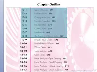
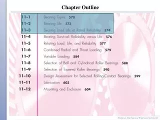
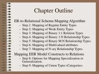
Chapter Outline. Introduction Chemical Machining Electrochemical Machining Electrochemical Grinding Electrical-Discharge Machining Laser-Beam Machining Electron-Beam Machining Water-Jet Machining Abrasive-Jet Machining Hybrid Machining Systems

E N D
Chapter Outline • Introduction • Chemical Machining • Electrochemical Machining • Electrochemical Grinding • Electrical-Discharge Machining • Laser-Beam Machining • Electron-Beam Machining • Water-Jet Machining • Abrasive-Jet Machining • Hybrid Machining Systems • Economics of Advanced Machining Processes • Fs-laser nanomachining-optional
27.5 Electrical-Discharge Machining • The principle of electrical-discharge machining (EDM) (also called electrodischargeor spark-erosion machining) is based on the erosion of metals by spark discharges. FIGURE 27.10 (a) Schematic illustration of the electrical-discharge machining process. This is one of the most widely used machining processes, particularly for die-sinking applications.
27.5 Electrical-Discharge Machining FIGURE 27.10 (b) Examples of cavities produced by the electrical-discharge machining process, using shaped electrodes. The two round parts (rear) are the set of dies used in extruding the aluminum piece shown in front (see also Fig. 15.9b). (c) A spiral cavity produced by EDM using a slowly rotating electrode similar to a screw thread. (d) Holes in a fuel-injection nozzle made by EDM; the material is heat-treated steel. Source: (b) Courtesy of AGIE USA, Ltd.
27.5 Electrical-Discharge Machining Principle of operation • The basic EDM system consists of a shaped tool (electrode) and the workpiece connected to a DC power supply and placed in a dielectric (electrically nonconducting) fluid. • The material-removal rate can be estimated from the following approximate empirical formula • where MRR is in mm3/min, I is the current in amperes, and is the melting point of the workpiece in °C.
27.5 Electrical-Discharge Machining Principle of operation • The frequency of discharge or the energy per discharge, the voltage, and the current usually are varied to control the removal rate. • The removal rate and surface roughness increase with (a) increasing current density and (b) decreasing frequency of sparks.
27.5 Electrical-Discharge Machining Dielectric fluids • The functions of the dielectric fluid are to: • Act as an insulator until the potential is sufficiently high. • Provide a cooling medium. • Act as a flushing medium and carry away the debris in the gap. Electrodes • Electrodes for EDM usually are made of graphite, although brass, copper, or copper-tungsten alloys also are used. • It has been shown that tool wear is related to the melting points of the materials involved: the lower the melting point of the electrode, the higher is the wear rate.
27.5 Electrical-Discharge Machining Process capabilities • Electrical-discharge machining has numerous applications, such as the production of dies for forging, extrusion, die casting, injection molding, and large sheet-metal automotive-body components (die-sinking machining centers with computer numerical control).
27.5 Electrical-Discharge Machining FIGURE 27.11 Stepped cavities produced with a square electrode by the EDM process. The workpiece moves in the two principal horizontal directions, and its motion is synchronized with the downward movement of the electrode to produce these cavities. Also shown is a round electrode capable of producing round or elliptical cavities. Source: Courtesy of AGIE USA, Ltd.
27.5 Electrical-Discharge Machining Design considerations for EDM • The general design guidelines for electrical discharge machining are as follows: • Parts should be designed so that the required electrodes can be shaped properly and economically. • Deep slots and narrow openings should be avoided. • For economic production, the surface finish specified should not be too fine. • In order to achieve a high production rate, the bulk of material removal should be done by conventional processes (roughing out).
27.5.1 Wire EDM • Wire EDM is similar to contour cutting with a band saw. • Fig 27.12 shows the schematic illustration of the wire EDM process. As many as 50 hours of machining can be performed with one reel of wire, which is then discarded.
27.5.1 Wire EDM • Fig 27.13(a) shows the cutting a thick plate with wire EDM. (b) A computer-controlled wire EDM machine.
27.5.1 Wire EDM • The cutting speed generally is given in terms of the cross-sectional area cut-per-unit time. • Modern wire EDM machines (multiaxis EDM wire-cutting machining centers) are capable of producing three-dimensional shapes and are equipped with such features as: • Computer controls for controlling the cutting path of the wire and its angle with respect to the workpiece plane. • Multiheads for cutting two parts at the same time. • Features such as controls for preventing wire breakage. • Automatic self-threading features in case of wire breakage. • Programmed machining strategies to optimize the operation.
27.5.2 Electrical-discharge grinding • The grinding wheel in electrical-discharge grinding (EDG) is made of graphite or brass and contains no abrasives. • Material is removed from the workpiece surface by spark discharges between the rotating wheel and the workpiece. • This process is used primarily for grinding carbide tools and dies but also can be used with fragile parts, such as surgical needles, thin-walled tubes, and honeycomb structures.
27.5.2 Electrical-discharge grinding • Material is removed by chemical action (with the electrical discharges from the graphite wheel breaking up the oxide film) and is washed away by the electrolyte flow. • The material-removal rate in EDG can be estimated from the equation: where MRR is in mm3/min, I is the current in amperes, and K is a workpiece material factor in mm3/A-min.
27.6 Laser-Beam Machining • In laser-beam machining (LBM), the source of energy is a laser (an acronym for light amplification by stimulated emission of radiation), which focuses optical energy on the surface of the workpiece. FIGURE 27.14 (a) Schematic illustration of the laser-beam machining process. (b) and (c) Examples of holes produced in nonmetallic parts by LBM. (d) Cutting sheet metal with a laser beam. Source: (d) Courtesy of Rofin-Sinar, Inc.
27.6 Laser-Beam Machining • The cutting depth may be expressed as where t is the depth, C is a constant for the process, P is the power input, v is the cutting speed, and d is the laser-spot diameter. • Laser beams may be used in combination with a gas stream (such as oxygen) to increase energy absorption (laser-beam torch) for cutting sheet metals.
27.6 Laser-Beam Machining Process capabilities • Laser-beam machining is used widely for drilling, trepanning, and cutting metals, nonmetallic materials, ceramics, and composite materials. • Laser beams also are used for the following applications: • Welding. • Small-scale and localized heat treating of metals and ceramics to modify their surface mechanical and tribological properties. • Marking of parts, such as letters, numbers, codes, etc. • Engraving
27.6 Laser-Beam Machining • The inherent flexibility of the laser-cutting process—including its fiber-optic beam delivery, simple fixturing, low setup times, and the availability of multi-kW machines and two- and three-dimensional computer-controlled robotic laser-cutting systems—is an attractive feature.
27.6 Laser-Beam Machining Design considerations for LBM General design guidelines for laser-beam machining are: • Designs with sharp corners should be avoided, since they can be difficult to produce. • Deep cuts will produce tapered walls. • Reflectivity of the workpiece surface is an important consideration in laser-beam machining; because they reflect less, dull and unpolished surfaces are preferable. • Any adverse effects on the properties of the machined materials caused by the high local temperatures and heat-affected zone should be investigated.
Example 27.1 Combining laser cutting and punching of sheet metal The advantages of laser cutting are generally: (a) smaller batches, (b) the flexibility of the operation, (c) a wide range of thicknesses, (d) prototyping capability, (e) materials and composites that otherwise may be cut with difficulty, (f) complex geometries that can be programmed.
Example 27.1 Combining laser cutting and punching of sheet metal • - Two processes cover different but complementary ranges. • Machines have been designed and built that different processes and fixturing can be utilized jointly to their full extent but without interfering with each other’s operational boundaries. • The purpose of combining them is to increase the overall efficiency and productivity of the manufacturing process for parts that are within the capabilities of each of the two processes. For example, turret-punch presses have been equipped with an integrated laser head; the machine can punch or laser cut, but it cannot do both simultaneously.
Example 27.1 Combining laser cutting and punching of sheet metal Factors taken into account in such a combination with respect to the characteristics of each operation: the ranges of sizes, thicknesses, and shapes to be produced and how they are to be nested; processing and setup times, including the loading, fixturing, and unloading of parts; programming for cutting; process capabilities of each method, including dynamic characteristics, vibrations, and shock from punching (and isolation) that may disturb adjustments and alignments of the laser components.
27.7 Electron-Beam Machining • The energy source in electron-beam machining (EBM) is high-velocity electrons, which strike the workpiece surface and generate heat. • Electron-beam machining can be used for very accurate cutting of a wide variety of metals. • Surface finish is better and kerf width is narrower than those for other thermal cutting processes.
27.7 Electron-Beam Machining FIGURE 27.15 Schematic illustration of the electron-beam machining process. Unlike LBM, this process requires a vacuum, so the workpiece size is limited to the size of the vacuum chamber.
27.7 Electron-Beam Machining Plasma-arc cutting • In plasma-arc cutting (PAC) plasma beams (ionized gas) are used to rapidly cut ferrous and nonferrous sheets and plates. • Material-removal rates are much higher than those associated with the EDM and LBM processes, and parts can be machined with good reproducibility. • Plasma-arc cutting is highly automated today, using programmable controllers.
27.7 Electron-Beam Machining Design considerations for EBM • Additional considerations are: • Because vacuum chambers have limited capacity, parts or batches should match closely the size of the vacuum chamber for a high-production–rate per cycle. • If a part requires electron-beam machining on only a small portion of the workpiece, consideration should be given to manufacturing it as a number of smaller components and assembling them after electron-beam machining.
27.8 Water-jet Machining • The water jet acts like a saw and cuts a narrow groove in the material. • A pressure level of about 400 MPagenerally is used for efficient operation, although pressures as high as 1400 MPa can be generated. FIGURE 27.16 (a) Schematic illustration of the water-jet machining process.
27.8 Water-jet Machining FIGURE 27.16 (b) A computer controlled water-jet cutting machine. (c) Examples of various nonmetallic parts produced by the water-jet cutting process. Source: Courtesy of OMAX Corporation.
27.8 Water-jet Machining • The advantages of this process are: • Cuts can be started at any location without the need for predrilled holes. • No heat is produced. • No deflection of the rest of the workpiece takes place, thus the process is suitable for flexible materials. • Little wetting of the workpiece takes place. • The burr produced is minimal. • It is an environmentally safe manufacturing process. • It is relatively clean operation, used in food-proccesing.
27.8 Water-jet Machining Abrasive water-jet machining • In abrasive water-jet machining (AWJM), the water jet contains abrasive particles (such as silicon carbide or aluminum oxide), which increase the material-removal rate above that of water-jet machining. • In abrasive-jet machining (AJM), a high-velocity jet of dry air, nitrogen, or carbon dioxide containing abrasive particles is aimed at the workpiece surface under controlled conditions.
27.9 Abrasive-jet Machining FIGURE 27.17 (a) Schematic illustration of the abrasive-jet machining process. (b) Examples of parts made by abrasive-jet machining, produced in 50-mm (2-in.) thick 304 stainless steel. Source: Courtesy of OMAX Corporation.
27.10 Hybrid Machining Systems • Two or more machining processes are combined into one system • Abrasive machining + ECM • Abrasive machining + EDM • Abrasive machining + EC finishing • Water jet cutting + wire EDM • Milling + Laser ablation + Blasting • Machining + Blasting • ECM + EDM (=ECDM or ECSM) • Laser cutting + Punching (of sheet metals) • Forming + Machining + Joining
27.11 Economics of Advanced Machining Processes • Advanced machining processes have unique applications and are useful particularly for difficult-to-machine materials and for parts with complex internal and external profiles. • The economic production run for a particular process depends on the costs of tooling and equipment, the operating costs, the material-removal rate required, the level of operator skill required, as well as on secondary and finishing operations that subsequently may be necessary.
27.2 CASE STUDY Manufacture of Small Satellites • Reducing the size of satellites is important to reduce the cost of putting the satellite into orbit.
27.2 CASE STUDY Manufacture of Small Satellites • One of the main sources of weight is propulsion system. FIGURE 27.18 Propulsion system for a small satellite. (a) Miniaturized system suitable for a micro- or nanosatellite, and (b) selected propulsion system components. Source: Courtesy of R. Hoppe, VACCO Industries, Inc.
27.2 CASE STUDY Manufacture of Small Satellites • Manufacture of propulsion systems for micro- and nanosatellites: photochemical etching + diffusion-bonding FIGURE 27.19 Photochemically etched and blanked components for micro- and nanosatellites. (a) Mounting board incorporating fluid flow channels in an integrated package; (b) microscale valve spring placed next to a U.S. penny; and (c) fuel filter. Source: Courtesy of R. Hoppe, VACCO Industries, Inc.
27.2 CASE STUDY Manufacture of Small Satellites • Photochemical etching + diffusion-bonding processes FIGURE 27.20 Processing sequence for photochemical etching of microsatellite components: (a) Clean the raw material; (b) coat with photosensitive material. Source: Courtesy of R. Hoppe, VACCO Industries, Inc.
27.2 CASE STUDY Manufacture of Small Satellites • Photochemical etching + diffusion-bonding processes FIGURE 27.20 Processing sequence for photochemical etching of microsatellite components: (c) expose with photographic tool; (d) develop a resist image. Source: Courtesy of R. Hoppe, VACCO Industries, Inc.
27.2 CASE STUDY Manufacture of Small Satellites • Photochemical etching + diffusion-bonding processes FIGURE 27.20 Processing sequence for photochemical etching of microsatellite components: (e) etch; and (f) remove the resist. Source: Courtesy of R. Hoppe, VACCO Industries, Inc.
Concept Summary • Advanced machining processes have unique capabilities and utilize chemical, electrochemical, electrical, and high-energy-beam sources of energy. The mechanical properties of the workpiece material are not significant, because these processes rely on mechanisms that do not involve the strength, hardness, ductility, or toughness of the material. Rather, they involve physical, chemical, and electrical properties.
Concept Summary • Chemical and electrical methods of machining are suitable particularly for hard materials and complex shapes. They do not produce forces (and therefore can be used for thin, slender, and flexible workpieces), significant temperatures, or residual stresses. However, the effects of these processes on surface integrity must be investigated, as they can damage surfaces considerably, thus reducing the fatigue life of the product.
Concept Summary • High-energy-beam machining processes basically utilize laser beams, electron beams, and plasma beams. They have important industrial applications, possess a high flexibility of operation with robotic controls, and are competitive economically with various other processes. • Water-jet machining, abrasive water-jet machining, and abrasive-jet machining processes can be used for cutting as well as deburring operations. Because they do not utilize hard tooling, they have an inherent flexibility of operation.