Download
1 / 20
200 likes | 203 Views
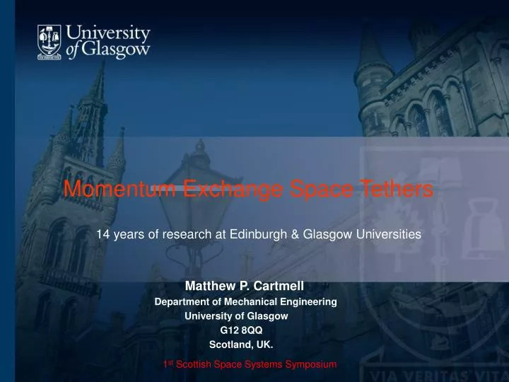
Momentum Exchange Space Tethers 14 years of research at Edinburgh & Glasgow Universities. Matthew P. Cartmell Department of Mechanical Engineering University of Glasgow G12 8QQ

E N D
Momentum Exchange Space Tethers14 years of research at Edinburgh & Glasgow Universities Matthew P. Cartmell Department of Mechanical Engineering University of Glasgow G12 8QQ Scotland, UK. 1st Scottish Space Systems Symposium
Momentum Exchange Space Tethers • Tsiolkovsky (1895) – proposed exploitation of gravity gradient force for an elevator, and rotating structures for artificial gravity • Tsander (1910) – suggested the use of a tapering cable to connect the Earth and the Moon • Artsutanov, Isaaks, and Pearson (1960s) – re-invented the space elevator • Gemini 11 & 12 – 1966 • Oedipus A – 1989 • TSS1 – 1992 • SEDS1 – 1993 • PmG – 1993 • SEDS2 – 1994 • Oedipus C – 1995 • TSS1R – 1996 • TiPS – 1996 • ATEx - 1998 US Naval Research Lab – TiPS on 20/06/96, Ralph (lower) and Norton (upper) joined by a 4km tether - the Tether Physics and Survivability Experiment.
Team members and their projects (1998-2010) Postdoctoral RAs: Dr Cristina D’Arrigo – Inertial parametric excitation of momentum exchange tethers Dr David I.M.Forehand – Analytical model and solutions for a librating MMET Dr Olga A.Ganilova – Payload soft landing dynamics Ph.D. Students: Dr Spencer Ziegler – MMET tether dynamics Dr David McKenzie – MMET tether dynamics & Space Web models Dr Christopher Draper – MMET risk & lifetime analyses, Dr Leo Yi Chen – MMET tether dynamics and control (discrete models) Christopher Murray – MMET Earth Moon mission architectures Norilmi Ismail – MMET tether dynamics (continuum models) M.Sc. Students: Gao Ji – Operational power budgets for MMETs Edith Mouterde – Feedback linearisation control simulations for MMETs Simone Lennert – Tether brake systems Claudia Gandara – Payload de-spin dynamics 1 Prabhanand Peerupalli – Payload de-spin dynamics 2 David Neill – Payload de-spin design concepts 1 Allan Barr – Payload de-spin design concepts 2 Amir Mubarak – Gyratory propulsion systems 1 Llewellyn Price – Gyratory propulsion systems 2 Ali Razavi – Payload soft landing dynamics David Dupuy – Design and material selection considerations for multi-line tethers
TiPs mission – 20 June 1996 Norton 4 km Tether Ralph Ralph & Norton - Ralph Kramden and Ed Norton, two US comedians who starred in the 1950s show The Honeymooners. Payloads connected together by a 4km tether to test gravity gradient stabilisation and libration effects.
Research Timeline 1981-2001 Edin. Univ. Abdn. Univ. Swan Univ. Edin. Univ. Glasgow Univ. 1991 Expt. verification 1996 ‘Rotators’? • In space? • - Scale • - Application • Materials • motor drive? 1997 ESTEC contract #1 1981 Unstable beam – accident! 1995 Q: can we scale up such systems? How much? Optimising KE? 1987 Theoret. Models of energy flows through paramet. oscillators. #2 1998 First Ph.D. student on ‘tethers’ – S.W.Ziegler MMET – modelled! ‘slingshot’ concept 1994 Publication: JSV, Watt & Cartmell, ‘An externally loaded parametric oscillator’ 1983 Definition of new combination instability in a parametrically excited beam = ½(B1+ B2) 2001 ESTEC contract #3 - ‘Staging’ - Scale Model! Response to ESTEC call for ‘novel space propulsion concepts’ ‘Space Tether’ - re-invented yet again? Partly, but with refinements! Symmetrical Motorised Momentum Exchange Tether
Research Timeline 2002-2008, and beyond… Glasgow University ….. • 1998-2008 • Deployers & brakes • Para. Ex, tether • Continuum model • Control sims • ‘Gyrator’ concept • SMAs & tethers 2005-2009 Thales-Alenia Aerospace contracts - 3 2002 ‘Project Aurora’ propulsion technology roadmap – MMET included! 2005-2006 Earth-Moon architecture 2006-2007 Space-Webs 2007-2009 Earth-Mars architecture 2002 Royal Society award and SSE participation.
Fundamentals A Space Tether on an orbit around a planet will tend to ‘hang’ if left undisturbed. This is called Gravity Gradient Stabilisation (GGS). A small tensile force is induced by this in the tether, causing it to appear to have some of the qualities of a rigid body. This shows a Motorised Momentum Exchange Tether (MMET) on a circular Earth orbit. The motor raises the energy level in the system and overcomes GGS and perturbational effects to generate a spin. It is this spin which can be used for propulsion of the payloads. sub-span 2, l sub-span 1, l Outrigger tether Propulsion Tether If V0is arranged to be around 7.62 km/s, and if can reach 3.15 km/s, then the outer payload will be at 10.77 km/s - and able to ESCAPE! This is using a tether for interplanetary transfer! E
Gravity Gradient Stabilisation An object of mass m, and radial position r from the centre of the Earth, which is orbiting the Earth is subjected to a gravitational force: The inwardly acting centripetal force on the body, due to its orbital motion, is given by: z At CoM: z CoM CoM (1) Outer case r0 r r r0 • Outer case (2) Inner case • r = r0 + z r = r0 - z for ‘short’ tethers! at (2) Inner case [Cartmell (2006)]
Dumb-bell Tethers in 3 Dimensions In this early model (1996-1998) a ‘spin plane’ was defined whose inclination relative to the equatorial orbit plane was defined by α. The angular spin coordinate is ψ. This modelling concept was superseded by a ‘projected spin’ coordinate, together with an inclination α. Both coordinates are required to define spin fully. E denotes the centre of the Earth and CoM is the centre of the tether – the location of the ‘facility’ which contains the motor drive, power supplies, controls, telemetry, etc. [Cartmell (1996-1998), Cartmell & Ziegler (1998-1999)]
γ • Generalised Coordinates: • R– length of position vector from E to CoM • - tether spin coordinate projected onto the ‘tether plane’ • - angular coordinate denoting out-of-plane orientation of tether θ – true anomaly i – inclination of tether plane to Earth equatorial plane γ – roll coordinate (along tether’s long axis) Modelling of the MMET in a non-equatorial Earth orbit R E 5 scalar equations of motion – nonlinear ODEs Motor Drive excites equations in and . [McKenzie (2004), Cartmell, McKenzie, McInnes (2004-2006)]
Obtaining practically useful Increments using ‘staging’ A series of calculations based on standard orbital mechanics gets the payload from Sub-Earth Orbit (SEO), with an apogee velocity of 7.3810 km/s, to LTO with a velocity of 10.7285 km/s. V for this system is 3.3475 km/s. The angular velocity of the facility in the rescue orbit PEO1 is peo1 = 0.01065 rad/s. The tip velocities, relative to the centres of tether rotation, are Vleotip= 0.8730 km/s and Veeotip= 0.7980 km/s. Design calculations suggest that payloads of up to 1000 kg, and 3.25 GPa strength Spectra2000TMcan be used for the tether.
Environmental Design The HoytetherTM Load taken by Sec. Lines Load also shared with other Sec. Lines Broken Pri. Line [Graphic: Tethers Unlimited Inc.] Problem: How do we prevent it stretching (and the cross-section reducing as it does so)?
Adding axial elasticity to an MMET model We start by simplifying the model by using a circular equatorial orbit, so there are just two generalised coordinates: and Lx. Chen & Cartmell (2007), Chen (2010)]
Axial Elasticity Model – Initial Performance [Chen & Cartmell (2007)]
Generating more data – scale model testing MMET shown on ice at Braehead Centre, Glasgow, April 2001, with 9.4 kg payloads, 1 metre tethers, and 80 W motor drive power. Radio control used for (i) cold gas start-up thrusters (long cylinders on each payload), (ii) drive motor (contained in central facility and driving the alloy bar to which the tethers are connected), (iii) payload release actuators (stepper motor driven actuators on each payload). Length scale is 1:40000. Sponsored by ESA/ESTEC, April 2001. [Cartmell & Ziegler (2001)]
Lunar Mission MMET hardware - Payloads cap 2.3 m container end cone 2.2 m Structure: 7000 series Al - longerons and rings,flange joints, estimated internal volume of the container: 5m3, attitude thrusters on the external surface, fuel pipelines divided into two parts re the container-cone joint, 8 external lugs integral with the primary structure for capsule lifting. [Villanti, Canina, Cartmell, Vasile & Murray (2006)]
Payload Delivery & Retrieval hardware -Passive payload -No expendables on the tether -Large capture volume with low mass -Only one active component -Minimises shock loading on the tether [Villanti, Canina, Cartmell, Vasile & Murray (2006)]
Can the Tether be extended, conceptually? Yes! We have proposed a ‘Space-Web’ concept – reflectors, telescopes, interferometers, SBSP. Telescope/reflector web Robot crawler Masses 1 to 3 could form the apex points of a triangular web. Other shapes are equally possible. [McKenzie, Cartmell, Vasile (2006)]
Modelling the Web C B A Start with arbitrary shape – triangle and define edge nodes and midpoint, then divide into two and define new edge nodes and midpoints, then divide into three and re-define, leading to division into n divisions and definitions of edge nodes and midpoints. A B C