Download
1 / 44
580 likes | 1.29k Views
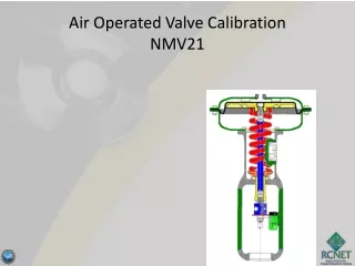
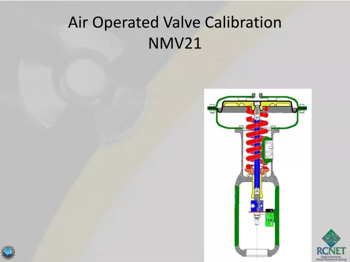
Air Operated Valve Calibration NMV21. Terminal Objective.

E N D
Terminal Objective Given the necessary references, tools and test equipment, the technician will maintain pneumatic control valve components. Mastery will be demonstrated by completion of all Laboratory Practical Evaluations and scoring at least 80 % on an end of course exam.
Enabling Objectives Given an example or illustration, identify the types of control valves. Given an example or illustration, identify components associated with various valve types. Identify flow characteristics of various valves . Describe the operation of Pneumatic Actuators. Describe the critical elements associated with valve packing. Describe the operation of a flapper/nozzle detector. Describe the operation of a booster relay.
Enabling Objectives Describe the operation of air regulators. Describe the operation of valve position indication devices. Describe the use and operation of solenoid valves on air operated valves. Calibrate a Fisher 546 I/P Converter. Benchset diaphragm actuators. Calibrate Valve Positioners. Calibrate a Steam Bypass Control Valve.
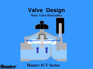
FLOW Typical Globe Valves
FLOW Typical Butterfly Valves
SPRING FLOW FLOW Typical Check Valves
Valve Body Two Way Three Way Packing Flange Packing Cage Bonnet Valve Stem Valve Plug Seat Typical Globe Valve Construction
Various plugs shown in yellow Basic Plug Disc Composition Disc Guided Disc Some Globe Valve Plugs (discs)
FLOW FLOW Reverse Action(down to open) Double-Ported Globe Valve Globe Valve Ports and Action
Packing Flange Valve Stem Packing Bonnet Valve Seat Split Disc Solid Disc Typical Gate Valve Construction Valve Body
Packing Packing Packing Flange Valve Stem Valve Body Valve Disc Valve Seat Bearings Typical Butterfly Valve Construction
Valve Body Valve Seat Ball Valve Stem Bearings Bonnet Packing Packing Flange Typical Ball Valve Construction
100 75 Linear 50 % Flow Quick Opening Equal Percentage 25 Ideal FlowCharacteristics 0 25 100 75 50 % Valve Travel
Linear Equal Percentage Quick Opening Plug and Seat Flow Characterization
Spring Seat Spring Adjustor Stem Connector Travel Indicator Disk Diaphragm Casings Diaphragm Diaphragm Plate Seal Bushing Actuator Spring Actuator Stem Indicator Scale Yoke Diaphragm Actuator Construction
O-Ring Positioner Piston Rod Extension Upper Seal Bushing Cylinder Piston / Rod Lower Seal Bushing Piston Rod Boot Yoke
PackingGlandFollower Valve Stem Braided Ring Graphite Rings Braided Ring CarbonSpacer
Travel Adjustment Screw Pivot Pin Input Cam Beam Nozzle Follower Assembly Rotary Shaft Arm Flapper Input Bellows Fisher 3582Positioner Construction Nozzle
Roller Wear and Cut Guide Wear Guide & Roller Bearing Beam Wear caused by Guide (“locked valve position”) Cam Beam Off Center Wear caused by siezed roller Cam Fisher 3582 Wear Points
Input Bellows Range Spring Beam Horizontal Relay Cylinder (Top) Bias Spring Air Supply Bellows Post 3570 Positioner Construction Cylinder (bottom) Vertical Relay Input
Operating Lever Cover / Gasket Clamping Screw Lever Locking Pipe Plug Contacts NAMCO Position Switches
De-Energized Energized S S 2-Way S S 3-Way S S 4-Way P&ID symbols for SOV’s
Cover Core Assembly Yoke Body Coil Disc Assembly End Cap Housing Solenoid Base Typical SOV Construction
Zero Air Supply Output Torque MotorAssembly Span Shunt Pivot(behind Torque Motor) Input Fisher 546 I/P Construction