Advanced Aircraft Communication Systems: Technology and Applications
470 likes | 1.15k Views
Explore the intricate world of aircraft communication systems, from electromagnetic waves and frequency modulation to satellite communications and TCAS. Learn about HF, VHF, UHF radio systems and their critical role in aviation safety. Discover the principles of transponders and the importance of TCAS in preventing mid-air collisions. Stay informed about the historical incidents in aviation and the significance of communication technology advancement for air traffic control and passenger safety.

Advanced Aircraft Communication Systems: Technology and Applications
E N D
Presentation Transcript
Electromagnetic Waves Vertically polarized waves – Vertically mounted antenna. Horizontally polarized waves – Horizontally mounted antenna.
Frequency and Modulation Amplitude modulation Frequency modulation
Radio Frequency Spectrum Simplified radio frequency spectrum – civil use
Radio Frequency Spectrum Broad categorization Letter designation of radio frequency bands of higher-frequency bands
Aircraft Communication Systems Voice communication (analog) versus data-link communication (digital). Voice communication – After selecting the appropriate communications channel on the channel selector, the pilot transmits a message by pressing the transmit button which connects the microphone to the appropriate radio. The voice message is used to modulate the carrier frequency, and it is this composite signal that is transmitted. The receiver demodulates the incoming signal to recover the original voice component. The advantage of this very simple method of transmission is that it is extremely easy to use all the pilot has to do is speak.
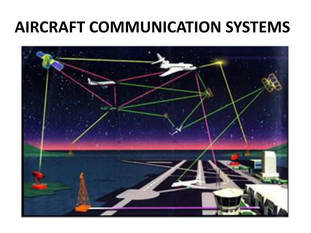
Aircraft Communication Systems High-Frequency (HF) radio transmit/receive. Very High Frequency (VHF) radio transmit/receive and an Aircraft Communications Addressing and Reporting System (ACARS). Selective Calling (SELCAL) – HF/VHF. Ultra High-Frequency (UHF) radio transmit/receive (225 to 400 MHz) – mainly used in military communications. Satellite Communications (SATCOM) including passenger telephone communications. Aircraft transponder and Air Traffic Control (ATC) mode A/C and S. Traffic Collision and Avoidance System (TCAS).
Aircraft Communication Systems Boeing 777 antennae locations
Very High Frequency Very High Frequency (VHF) voice communication is probably the most heavily used method of communication used by civil aircraft. The VHF band for aeronautical applications operates in the frequency range 108 – 136 MHz with a channel spacing of 25 kHz. VHF signals will only propagate over line of sight. This line-of-sight property is affected by the relative heights of the radio tower and aircraft. R (nautical miles)
Very High Frequency Typical ACARS (VHF data-link) configuration – 131.55 MHz
High Frequency High Frequency covers the communications band between 3 and 30 MHz and is a very common communications means for land, sea, and air. The primary advantage of HF communications is that this system offers communication beyond the line of sight. HF communications are one of the main methods of communicating over long ranges between air and ground during oceanic and wilderness crossings when there is no line of sight between the aircraft and ground communications stations. HF Data Link (HFDL) offers an improvement over HF voice communications owing to the bit encoding inherent in a data link message format.
High Frequency An HFDL service is provided by ARINC using a number of ground stations. These ground stations provide coverage out to nearly 2700 nautical miles and on occasion provide coverage beyond that.
Satellite Communications Satellite communications provide a more reliable method of communications using the International Maritime Satellite Organization (INMARSAT) satellite constellation which was originally developed for maritime use. Airborne SATCOM terminal transmit frequency – 1626.5 to 1660.5 MHz, receive frequency – 1530 to 1559 MHz A SATCOM system typically comprises the following units: Satellite Data Unit (SDU). Radio Frequency Unit (RFU). Amplifiers, Diplexers/Splitters. Low-gain antenna. High-gain antenna.
Satellite Communications SATCOM – Principle of Operation
Air Traffic Control Transponder Principle of Transponder operation
Air Traffic Control Transponder Airborne transponder equipment
Air Traffic Control Transponder Mode A – aircraft identification. Mode C – aircraft’s identifier + altitude information. Mode S (mode Select) – aircraft’s identifier (unique 24-bit address) + aircraft azimuth bearing information. Mode S transmissions – 56 or 112 bit formats called frames. Mode S categories – 56 bit surveillance formats, 112 bit communication formats with a 56 bit data field and 112 bit communication formats with an 80 bit data field.
Mid-air Collision (without TCAS) CharkhiDadri(India) mid-air collision (12 November 1996) The worst mid-air accident in aviation history so far Total fatalities: 349 SaudiaBoeing 747-100B UN-76435, the Kazakhstan Airlines (departing from New Delhi to Saudi) aircraft (arriving to New Delhi)
Mid-air Collision (with TCAS) Überlingen(Germany) mid-air collision (1 July 2002) Total fatalities: 71 RA-85816, Bashkirian Airlines DHL Boeing 757 (from Moscow to Barcelona) (from Bahrain to Brussels)
Traffic Collision and Avoidance System (TCAS) The TCAS was developed in prototype form during the 1960s and 1970s to provide a surveillance and collision avoidance system to help aircraft avoid/reduce mid-air collisions. It was certified by the FAA in the 1980s and has been in widespread use. The system comprises two elements: a surveillance system and a collision avoidance system. TCAS detects the range, bearing and altitude of aircraft in the near proximity for display to the pilots. TCAS transmits a mode C interrogation (1030 MHz) search pattern for mode A and C transponder equipped aircraft and receives replies (1090 MHz) from all such equipped aircraft. In addition, TCAS transmits one mode S interrogation for each mode S transponder equipped aircraft, receiving individual responses from each one.
Traffic Collision and Avoidance System (TCAS) Mode A – range and bearing, mode C – range, bearing, and altitude and mode S – range, bearing, and altitude with a unique mode S reply. Aircraft TCAS equipment: radio transmitter and receiver, directional antennae, a computer, and flight deck display. Whenever another aircraft receives an interrogation, it transmits a reply and the TCAS computer is able to determine the range (from the time taken to receive the reply). The directional antennae enable the bearing of the responding aircraft to be measured. TCAS can track up to 30 aircraft but only display 25, the highest-priority targets being the ones that are displayed.
Traffic Collision and Avoidance System (TCAS) TCAS equipment and displays (Courtesy: Honeywell)
Traffic Collision and Avoidance System (TCAS) Location of TCAS equipment
Traffic Collision and Avoidance System (TCAS) TCAS is unable to detect aircraft that are not carrying an appropriately operating transponder or that have unserviceable equipment. A transponder is mandated if an aircraft flies above 10,000 ft or within 30 miles of major airports. TCAS I indicates the range and bearing of aircraft within a selected range, usually 15 – 40 nautical miles forward, 5 – 15 nautical miles aft, and 10 – 20 nautical miles on each side. The collision avoidance system element predicts the time to, and separation at, the intruder's closest point of approach. These calculations are undertaken using range, closure rate, altitude, and vertical speed.
Traffic Collision and Avoidance System (TCAS) TCAS I – traffic advisory (TA) to alert the crew that closing traffic is in the vicinity via the display of certain coloured symbols. Upon receiving a TA, the flight crew must visually identify the intruding aircraft and may alter their altitude by up to 300 ft. A TA will normally be advised between 20 and 48 seconds before the point of closest approach with a simple audio warning in the flight crew's headsets: ‘TRAFFIC, TRAFFIC’. TCAS II provides traffic advisories and resolution advisories (RA). TCAS II determines the relative motion of the two aircraft and determines an appropriate course of action. The system issues an RA via mode S, advising the pilots to execute the necessary manoeuvre to avoid the other aircraft.
Traffic Collision and Avoidance System (TCAS) An RA will usually be issued when the point of closest approach is within 15 and 35 seconds and the deconfliction symbology is displayed coincident with the appropriate warning. A total of ten audio warnings may be issued. RA examples: ‘CLIMB, CLIMB, CLIMB’. ‘DESCEND, DESCEND, DESCEND’. ‘REDUCE CLIMB, REDUCE CLIMB’. Finally, when the situation is resolved, ‘CLEAR OF CONFLICT’. TCAS II – Integration required between ATC mode S transponders, TCAS, displays, audio system and annunciators.
Traffic Collision and Avoidance System (TCAS) TCAS II block diagram
Traffic Collision and Avoidance System (TCAS) TCAS Volume
Traffic Collision and Avoidance System (TCAS) Interrogation/Reply between TCAS systems
Traffic Collision and Avoidance System (TCAS) Standardized symbology for TA display
Traffic Collision and Avoidance System (TCAS) Typical resolution advisory (RA) indications (VSI)
Traffic Collision and Avoidance System (TCAS) Combined traffic advisory/resolution advisory display
Reference(s) Ian Moir and Allan Seabridge, Civil Avionics Systems, Professional Engineering Publications, 2003. Cary R. Spitzer, The Avionics Handbook, Chapter 18, CRC Press, 2001. Further Readings: http://en.wikipedia.org/wiki/Traffic_collision_avoidance_system http://www.aerowinx.de/html/tcas.html TCAS II/ACAS II Collision Avoidance System User’s Manual, Honeywell Inc.