Download

1 / 17
170 likes | 782 Views
The forming characteristics of radial-forward extrusions. Journal of Materials Processing technology , 15 June 2001. Y.S. Lee, S.K. Hwang, Y.S. Chang, B.B. Hwang. Presented by, Douglas Merrell September 15, 2004. Introduction.

E N D
The forming characteristics of radial-forward extrusions Journal of Materials Processing technology, 15 June 2001 Y.S. Lee, S.K. Hwang, Y.S. Chang, B.B. Hwang Presented by, Douglas Merrell September 15, 2004
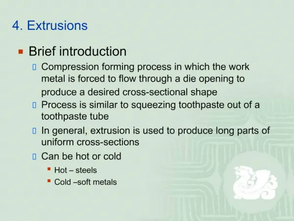
Introduction • The four basis types of extrusion are: direct (forward), indirect (backward), hydrostatic, and impact • New types of extrusion are being developed including radial extrusion
Introduction • In conventional extrusions material flows parallel to the punch or die • In radial extrusions the materials flow perpendicular to the punch or die
Examples of Radial Extrusion Parts Radial Extrusion is used to create universal joints, tube fittings and differential gears
Introduction • The researchers developed a model using the rigid-finite element method • Using this model they were able to simulate changes in design parameters • Then they were able to determine the effect of certain parameters on the power requirements
References [1] S. Kalpakjian, Manufacturing Processes for Engineering Materials, 2nd Edition, Addison-Wesley, USA, 1991, p. 363. [2] J. A. Pale, T. Altan, Development of equipment and capabilities for investigation of the multi-action forming of complex parts, Eng. Res. Center Net Shap Manuf. (1989) 8. [3] M. J. Saran, Journal of Materials Processing Technology. 27 (1991) 279. [4] Air Force Materials Laboratory, Forging Equipment, Materials and Practices, Metals and Ceramics Information Center, 1973. p. 164. [5] E. Paul De Garmo, Materials and Processes in Manufacturing, Macmillan, New York, 1967, p. 27. [6] E. Paul De Garmo, Material Properties and Manufacturing Processes, Malloy, Ann Arbor, MI, 1966, p. 31. [7] J. Datsko, Material Properties and Manufacturing Processes, Malloy, Ann Arbor, MI, 1966, p. 31. [8] Metals Handbooks, The Materials Information Society, Vol. 2, 10th Edition, p. 104 [9] S. Kobayahi, S.I. Oh, T. Altan, Metal Forming and the Finite Element Method, Oxford University Press, London, 1989, p. 30. [10] T. Huziyoshi, Die and Moulding, Daily Tech. Press, Tokyo, 1989, p. 446. [11] S. H. Lee, Forming characteristics of radial extrusion, Master Dissertation, Inhan Graduate School, Inchon, 1999, p. 20.
Model Part b = bottom thickness d0= billet diameter dA= mandrel diameter h0= billet height h1= workpiece height hst= punch stroke rA = die radius ru = deflection radius rG = mandrel radius Ss = gap height SR = annular gap width Sw = wall thickness Billet diameter Billet height Punch stroke Mandrel diameter Die radius Deflection radius Mandrel radius Gap height 16mm 70mm 40mm 28mm 2mm 2mm 2mm 4mm
Material Properties • Using AA 6063 Aluminum alloy • Cold working (strain rate not a factor) Calculated from σy, E, e, and Su
Simulation Maximum pressure is 3257 MPa
Simulation Verification that the model matches experimental tests Accurate to within 5%
Design Parameters • This paper choose to study: • Mandrel diameter (dG) • Die radius (rA) • Friction factor (m) • From previous studies [11] the gap height was known to have a large effect on the load. It was held constant. b = bottom thickness d0= billet diameter dA= mandrel diameter h0= billet height h1= workpiece height hst= punch stroke rA = die radius ru = deflection radius rG = mandrel radius Ss = gap height SR = annular gap width Sw = wall thickness
Friction Factor Friction has a large effect after 12.5 mm
Mandrel Diameter Shows the effect of the mandrel diameter on the load requirements. The greater the diameter the greater the load necessary.
Die radius As the die radius gets larger the force requirements get smaller, but the die radius has the least effect of all the design parameters
Conclusions • The friction factor has a large influence on the mandrel load but not on the punch load • The load increases with the mandrel diameter and the friction factor • The load decreases slightly with an increase in the die radius
Conclusions • The mandrel diameter has the greatest effect and the die radius has the least • Each of the design parameters had little effect on the punch load • The punch and mandrel loads are similar during the radial extrusion but diverge at the start of forward extrusion